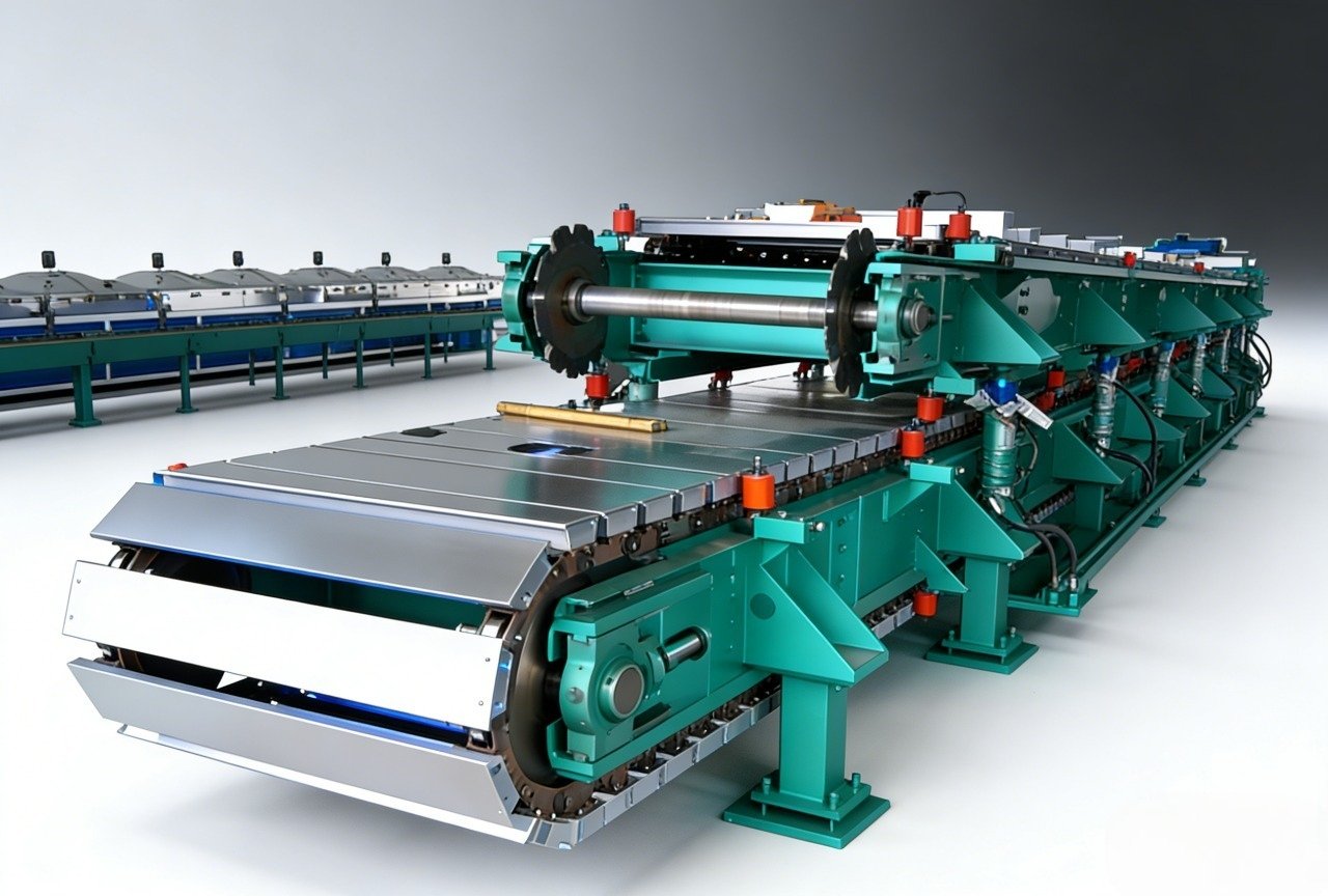
Long fiber injection with polyurethane looks simple in a video and becomes difficult on the plant floor. A chopper cuts glass roving, a mixing head wets the fibers with polyurethane, and a robot sprays the mixture into an open mold. The hard part is not the concept. It is the interaction among fiber length, mix ratio, shot time, robot speed, and mold temperature. When those variables drift, the result is usually not a slightly weaker part. It is a batch of dry-fiber zones, resin-rich areas, or density variation that only appears after demolding.
This article explains what LFI equipment actually has to do, which process parameters matter most, and how to evaluate a line before you commit to tooling.
What Long Fiber Injection with Polyurethane Actually Is
Long fiber injection, often shortened to LFI, is a process for producing fiber-reinforced polyurethane parts without a preform. Chopped glass fibers are cut at the mixing head and sprayed into an open mold together with a two-component polyurethane mixture. The mold then closes, the material cures, and the part is demolded.
That is the critical difference from structural reaction injection molding, or SRIM. In SRIM, a fiber preform is placed in the mold first and the resin is injected around it. In LFI, the fibers are cut, dispersed, and wetted in the same step. This removes the preform manufacturing step, but it also moves the quality burden to the mixing head, chopper, and the synchronization between fiber feed and polyurethane output.
The matrix is normally an MDI-based polyurethane system supplied as a polyol component and an isocyanate component. Glass roving is fed from a creel into a cutter mounted near the mixing head. Fiber length is determined by the cutter setup and the roving feed rate. The part is built up layer by layer in the open mold before pressing, so fiber orientation is mostly in-plane rather than truly three-dimensional.
For acceptance testing, LFI parts are normally checked by the same composite test logic used for other fiber-reinforced plastics: flexural properties, tensile properties, and glass content. Glass content is typically verified by calcination or ignition loss, while mechanical performance is checked by flexural or tensile methods [1][2][3][4].
Where LFI Is Used
LFI is used where a large, stiff, impact-resistant part has to be produced without the labor and cycle time of a hand-layup or preform process. Common applications include:
- Automotive bumper carriers, dashboard carriers, door modules, underbody shields, and interior panels
- Agricultural and construction vehicle hoods, roofs, fenders, and covers
- Building panels, machine housings, and industrial enclosures
- Parts that need an outer skin quality, low density, and controlled stiffness in specific areas
LFI is not the best answer for every composite part. If the part is small, highly three-dimensional, or requires very high fiber volume fraction, a different process may fit better. But for medium-to-large parts with moderate fiber loading and complex geometry, LFI can reduce manual handling and produce repeatable parts from shot to shot.
Equipment Basics for an LFI Line
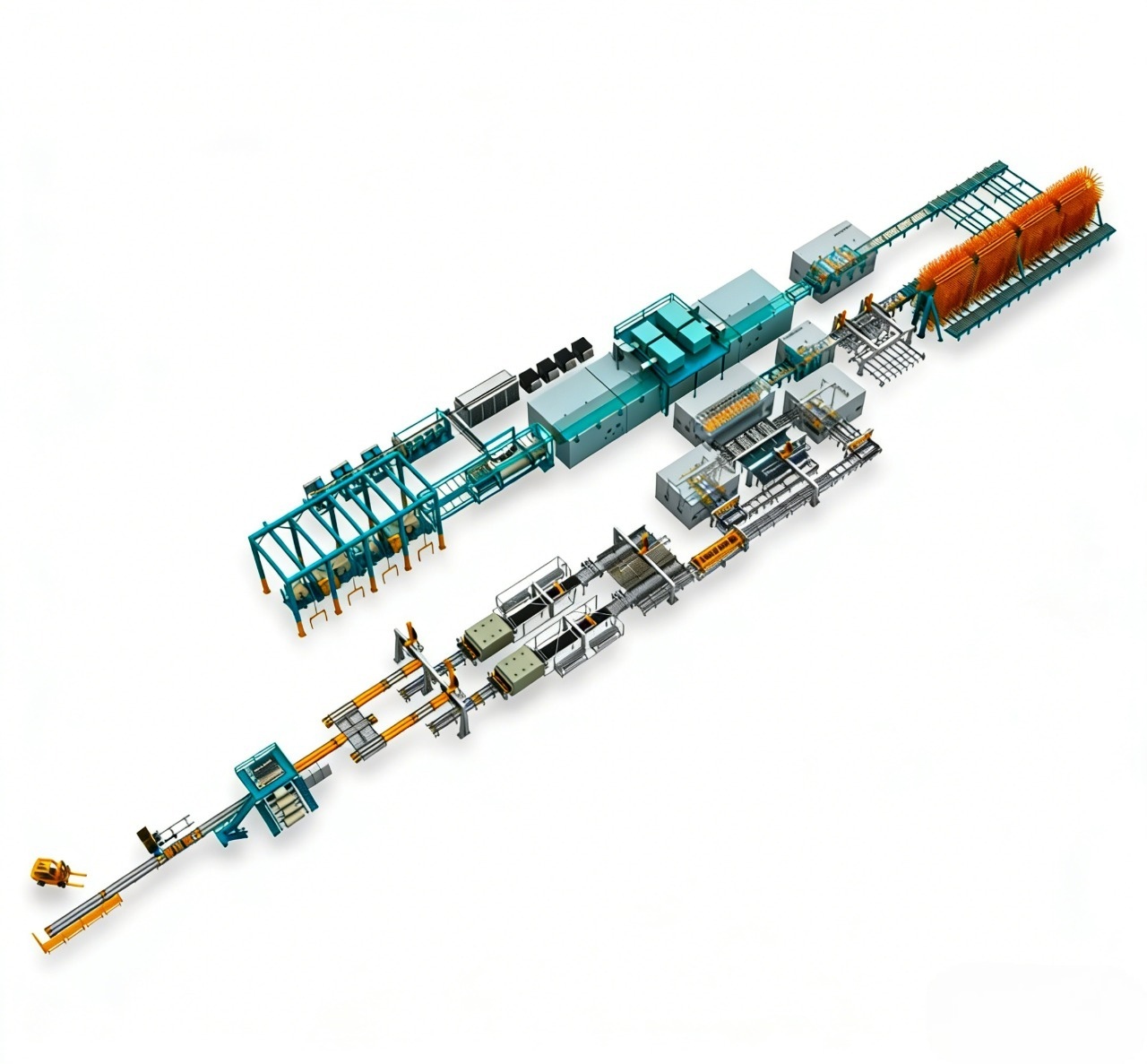
An LFI line is not a single machine. It is a small production cell made up of raw-material conditioning, metering, the mixing head with fiber cutter, a mold carrier or press, and the motion system that moves the spray pattern.
Raw Material Conditioning
Polyol and isocyanate need stable temperature and, in many cases, conditioned feeding. Polyol blends may require agitation to keep fillers or additives in suspension. Isocyanate requires moisture protection. A day-tank arrangement with recirculation and temperature control is usually part of the cell, even when the line itself is compact.
Metering and Mixing System
The metering and mixing system is where most LFI quality problems begin. A small drift in isocyanate or polyol output changes viscosity, wet-out, and cure behavior before it changes shot weight enough to be obvious. The mixing head must also combine the polyurethane stream with chopped glass in a stable spray cone. If the spray cone collapses or the fiber distribution shifts, the mold is still filled, but the part is not homogeneous.
LFI shares many process-control requirements with other polyurethane injection processes, especially around ratio stability and mold fill. <Low Pressure PU Foam Injection Machine for Custom Molding: Process & Parameters> covers the parameter set needed for custom molding and how to verify it before part quality drifts.
Fiber Chopper and Wet-Out
The fiber chopper is usually mounted on or next to the mixing head. Glass roving is pulled into a cutter unit, cut to a set length, and blown into the polyurethane spray pattern. Three things have to stay synchronized:
- Roving feed speed
- Chopper speed
- Robot or linear-axis travel speed
When the head moves quickly and the chopper stays at a fixed speed, the fiber mass deposited per square meter drops. When the robot slows or dwells, the local fiber content rises. That is why high-quality LFI cells use coordinated motion and chopper control rather than treating fiber feed as a constant.
Mold Carrier and Press
The mold is usually mounted on a hydraulic press, shuttle table, or rotary table. The carrier has to provide enough clamping force for the part area, keep the two mold halves aligned, and allow the demolded part to be removed without damaging the surface. Mold temperature is controlled because it affects the polyurethane reaction rate, surface cure, and cycle time. The correct temperature is determined by the PU system and part thickness, not by a generic setting.
Ventilation and Mold Release
LFI spraying creates aerosol and fiber dust, so the cell should include extraction and operator protection. Mold release is also a process variable. An inconsistent release application changes cycle time, surface finish, and the amount of manual correction required after demolding.
Process Parameters That Matter Most
The most useful way to look at LFI process control is by what each parameter changes.
| Parameter | What it affects | How to verify |
|---|---|---|
| Polyol-to-isocyanate ratio | Wet-out, cure speed, hardness, part strength | Shot calibration, mixing-head checks |
| Fiber length | Impact behavior, stiffness, surface quality | Chopper inspection, fiber-length checks |
| Fiber mass fraction | Mechanical properties, weight, cost | Burn-off or calcination test [2][3] |
| Shot size | Fill, flash, density, part weight | Serial shot-weight logging |
| Robot speed and path | Fiber distribution, thickness consistency | Part-section measurement, visual checks |
| Mold temperature | Cure rate, surface finish, demold time | Mold thermocouple logging |
| Clamp pressure | Flash formation, part thickness | Press pressure verification |
The difficult part is that none of these parameters is independent. If you raise fiber content without increasing polyurethane output, you may create dry glass. If you lower mold temperature, you may improve pot life but increase cycle time. If you increase robot speed for output, you may reduce wet-out.
The correct approach is to define a process window before production, then verify that every shot stays inside that window. If your target is a large structural part, the first step is usually a shot-size and fiber-content review, not a machine quotation. Send the part drawing and target glass content to info@haifeng-automation.cn. The equipment conversation should start only after the process window is clear.
Common Defects and Equipment-Related Causes
LFI defects usually look like material problems but often trace back to equipment settings.
| Defect | Likely equipment-related cause | Control action |
|---|---|---|
| Dry glass bundles | PU output too low for fiber feed, spray cone too narrow, ratio drift | Check metering output, head pressure, fiber-to-output synchronization |
| Resin-rich areas | Chopper feed interruption, clogged cutter, robot speed too low | Inspect chopper blades, roving tension, and motion path |
| Density variation | Uneven spray pattern, shot-size error, mold temperature variation | Verify robot path, shot weight, and mold thermocouples |
| Fiber clumps | Static, roving tension, worn cutter parts | Clean feed path, replace worn parts, check grounding |
| Porosity or blisters | Moisture, entrapped air, release-agent volatiles, low clamp force | Dry feed materials, check degassing and press force |
| Poor surface finish | Mold temperature, release coverage, flash, fill pattern | Adjust mold release, temperature, and fill sequence |
Equipment Selection Checklist
Before choosing an LFI machine or turnkey cell, work through these questions:
- What is the projected area and maximum shot weight of the part?
- What glass fiber length and mass fraction does the part need?
- Is the part open-mold sprayed and pressed, or does it need a more complex fill sequence?
- What mold carrier style fits the available floor space and demolding direction?
- Does the mixing head need to be robot-mounted, linear-axis-mounted, or fixed?
- How will fiber feed be synchronized with head movement?
- What recipe, shot, and alarm records must be stored for traceability?
- What is the target cycle time, including spray time, cure time, and demolding?
- What ventilation, safety, and maintenance access does the cell require?
If the answer to any question is “we do not know yet,” the first purchase should not be the machine. It should be a process definition. A line that cannot hold a stable spray pattern and ratio will not become capable later by adding more control screens.
Engineering Support for Your LFI Line
Long fiber injection is a process integration problem, not a single-machine purchase. Haifeng Polyurethane Machinery supplies metering systems, mixing heads, and turnkey production-cell integration for polyurethane composite applications. If you are evaluating an LFI line, send your part geometry, target glass content, and required output to info@haifeng-automation.cn or WhatsApp +86 13566296633. The most useful first step is a process-window review before tooling is fixed.
Frequently Asked Questions
What is the difference between LFI and SRIM?
LFI cuts and sprays glass fibers directly into the open mold together with the polyurethane mixture. SRIM places a separately manufactured fiber preform into the mold and injects resin around it. LFI removes the preform step but requires close synchronization between fiber cutting and polyurethane output.
Does LFI require a preform?
No. That is one of the main advantages. The fiber reinforcement is created at the mixing head and sprayed into the mold, so there is no separate preform manufacturing or handling step.
What fiber length is typically used in LFI?
Fiber length is process-dependent. Many production applications use chopped glass in the 12.5 to 100 mm range, with part geometry and impact requirements determining the actual setting. Longer fibers can improve impact resistance but make uniform wet-out more difficult.
What causes dry glass fibers in an LFI part?
Dry glass usually comes from too little polyurethane output for the fiber feed rate, a disturbed spray cone, ratio drift, or insufficient mixing. Chopped fiber that is not wetted into the polyurethane stream will show up as dry bundles inside the part.
Can LFI produce a high-quality surface?
Yes, when the outer surface is molded against a controlled mold face. Surface quality depends on mold temperature, mold release, fill pattern, and the condition of the tool surface. LFI is not automatically a Class A process; surface results come from the same molding discipline required in any polyurethane process.
What kind of data should an LFI machine record?
The cell should log shot size, component ratio, head movement, chopper output, mold temperature, clamp pressure, and alarms. Without those records, a recurring defect is difficult to separate from a random event.
References
- ISO 14125:1998, Fibre-reinforced plastic composites — Determination of flexural properties.
- ISO 1172:2023, Textile-glass-reinforced plastics — Prepregs, moulding compounds and laminates — Determination of glass-fibre and mineral-filler content using calcination methods.
- ASTM D2584-18, Standard Test Method for Ignition Loss of Cured Reinforced Resins.
- ISO 527-4:2023, Plastics — Determination of tensile properties — Part 4: Test conditions for isotropic and orthotropic fibre-reinforced plastic composites.
If you’re interested, check out these related articles:
Low Pressure PU Foam Injection Machine for Custom Molding: Process & Parameters
Polyurethane Machinery 101: A Comprehensive Guide to Equipment Types and Engineering Selection
How to Design a PU Shoe Factory Layout