



Recirculation in a polyurethane metering system is not a warm-up routine. It is the reason the first gram of a shot arrives at the same ratio as the thousandth. While the mixing head is closed, the loop keeps both components moving from tank through pump and back, holding line pressure, temperature and filler suspension at the condition the recipe assumes. Remove it and every shot starts with material that has been standing still: slightly cooler, leaner in filler, and delivered at a pressure the pump has not yet rebuilt. The error on a single shot is small. The scrap it produces across a shift is not.
What Recirculation Actually Does in a Polyurethane Metering System
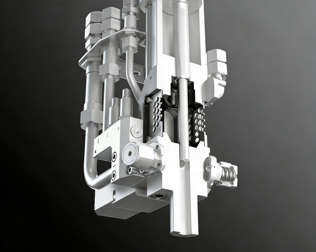
On a low-pressure machine the loop usually runs from the day tank through the feed pump, the metering pump, a filter and a heat exchanger, then to a three-way valve near the mixing head. While the head is closed, that valve sends material back to the tank. On a high-pressure machine the same work is done by a recirculation valve built into the mixing head, which keeps both streams circulating up to the impingement point. The hardware differs. The function does not.
The loop performs three jobs at once. It keeps the metering pumps at their operating point instead of stop-start. It keeps material moving through the places where heat is added or removed. And it gives you a continuous place to read pressure, flow and temperature, which is where most fault-finding starts.
Recirculation sits inside the machine’s flow path rather than beside it, so the machine type determines what the loop can hold steady. <Polyurethane Foam Machine: Types, Working Principle and Applications> covers how foaming, spraying and injection machines differ in working principle.
A machine with no loop, or with the loop closed off, holds a column of material between pump and head. That column is the subject of the next section.
Why a Static Line Fails in the First Seconds of a Shot
When the head opens, both pumps have to move from holding pressure to delivering a defined flow within milliseconds. Four things happen together. The line has to refill from the pump. Check valves reseat. Seal friction has to break away. And the closed-loop control has to correct a flow error it can only see after the error exists.
If both sides had identical pumps, identical viscosity and identical line length, those errors would cancel. In practice they rarely do. Polyol is usually far more viscous than isocyanate, and a filled polyol is more viscous still, so the A side lags the B side at start-up and the leading portion of the shot runs rich on the isocyanate side. The same lag appears wherever one component passes through a longer or colder path to the head.

The visible results are voids near the gate, short shots in the last cavity, and color that shifts from the first parts of a run to the rest. Because the fault appears only at the start of a shot, it survives every steady-state check. A ratio test run during continuous pouring passes and tells you nothing.
The test that exposes it is a segmented shot. Catch the first third, middle third and last third of one shot into separate containers, weigh each, and compare each weight against its share of the shot time. If the first segment is light, or its ratio is off, the machine is losing the start of the shot.
Recirculation removes most of this because the pumps never leave their operating point. The control loop is already trimming a live flow error before the head opens, so at switchover it is adjusting rather than recovering.
It does not remove the need to check. A loop running at the wrong return pressure, or through a partly blocked filter, gives the same false confidence as no loop at all.
How the Loop Controls Settling, Temperature and Entrained Air
Filler settles in the line as well as the tank
Calcium carbonate, glass microspheres, flame retardants and pigment pastes settle wherever local velocity drops low enough. A tank agitator addresses the tank. The line has its own quiet zones: horizontal runs, filter housings, the pockets around valve seats, the dead leg behind a pressure gauge. Recirculation keeps those zones moving between shots. Without it, material released at the next shot has had minutes or hours to stratify, and the pour begins leaner than the recipe specifies.
A loop does not repair a badly designed return. If the return line discharges above the liquid surface, or close to the agitator shaft where the tank vortexes, returning material picks up air faster than the vacuum can remove it. Return below the surface, away from the vortex.
Viscosity follows temperature, and temperature follows flow
A static line cools toward ambient. Metering pumps are positive displacement, so volume per revolution is set by geometry, but the filling of the pump chamber depends on inlet conditions. As polyol cools and thickens, the pressure drop across the filter and line rises, and the chamber fills less completely. Delivery falls before anything on the control screen reports a fault.
On the isocyanate side the risk is different. MDI-based isocyanates can crystallize when held below their storage temperature, and crystals that form in a line do not redissolve easily. A thermoregulated loop holds both components at set temperature and keeps the isocyanate out of that range.
Measure temperature at the return to the tank, not only at the tank. The return is the closest reliable proxy for what actually reaches the mixing head.
Degassing only works on material that passes through the vacuum
Vacuum degassing removes air from the volume that passes through the vacuum chamber. Material sitting in a line downstream of that chamber keeps whatever air it has picked up since. A recirculation loop gives the material repeated passes, so entrained air has more than one chance to reach the surface.
Haifeng Polyurethane Machinery builds one arrangement that attacks this from two sides: tank vacuum degassing combined with vacuum applied at the pouring head. The company states that this dual arrangement reduces bubble rate by more than 70 percent compared with its single-stage version. That figure is the manufacturer’s own claim. It has not been independently tested, and it describes that configuration rather than recirculation in general.
No loop removes air introduced after the vacuum. A worn seal at the mixing head, a loose suction connection, a return that splashes into the tank: these produce bubbles that appear only at the start of a shift or only after a filter change. That is an ingress problem, and additional degassing capacity does not address it.
What a Recirculation Loop Can and Cannot Support
Recirculation is often described in terms broader than it can carry. The table separates what a working loop actually establishes from what buyers commonly assume it establishes.
| Claim | What it can support | Do not infer |
|---|---|---|
| Return flow is continuous | material in the line is being exchanged | that the flow is high enough to keep a dense filler suspended |
| Return temperature reads at set point | the loop holds temperature where the sensor sits | that the material reaching the mixing head is at that temperature |
| Bubble rate fell after the loop was commissioned | the vacuum path is working on the material that passed through it | that no air enters downstream of the vacuum |
| Metering accuracy is quoted below one percent | steady delivery under the conditions named in the quotation | that the first second of a shot holds the same ratio |
| The loop runs throughout production | pumps stay at their operating point between shots | that settling inside the tank is controlled, which is the agitator’s job |
Each row can be tested rather than assumed. Return flow is measured, return temperature is read, bubble rate is compared before and after commissioning, metering accuracy is checked against the conditions named in the quotation, and settling is checked by weighing parts poured after idle. A supplier who cannot say which of these their loop was verified against has not verified any of them.
Where Recirculation Adds Cost or Risk
Every pass through the loop adds shear and heat. On a slow-reacting polyol system that is irrelevant. On a system with a catalyst, a curative or a short pot life, the loop behaves like a small reactor. Keep the recirculating volume small, keep loop temperature no higher than the process needs, and keep curative streams out of long hot paths.
Recirculating a filled stream means the same material passes the pump and the valve seats many times before it is poured. That is more wear than a single pass, and it is a real cost of the loop rather than a theoretical one. Wear appears first as a slowly widening ratio deviation that no single ratio check flags.
Pressure balance is the third cost. On a high-pressure impingement machine both components recirculate at high pressure. If the return pressures are unequal, the switch to injection starts from two different hydraulic states and the ratio shifts at the moment it matters most. Balance return pressures during commissioning, not only injection pressures.
There are also installations where a loop is the wrong trade. Where the batch is small, the material is thermally sensitive, and the start-of-shot volume is a small share of the pour, a purge routine sized to the shot often beats a loop that holds material hot for hours. The deciding question is how much material sits in the line between shots and how much it changes while it sits.
Bypass Loop or Head-Mounted Recirculation Valve
Three return paths are common, and they do not solve the same problem.
| Architecture | What stays in motion | Fits | Limitation |
|---|---|---|---|
| Pump-outlet bypass | the pump and the short return to the tank | single-component transfer and simple low-volume machines | the line to the mixing head stays static, so start-of-shot error remains |
| Three-way valve near the head | the full line from tank to valve | low-pressure machines with moderate line length | the final section between valve and head is static unless the valve sits at the head |
| Recirculation valve in the mixing head | the whole path to the impingement point, including head temperature | high-pressure impingement and multi-component systems | more seals and more complexity, and return pressures must be balanced |
Whichever architecture you choose, control the return with a defined back pressure. A free return into an open tank gives flow but no pressure reference, and flow without pressure says little about what the pump will do when the head opens.
Put a flow meter and a pressure gauge on the return, not only on the delivery side. Most loop faults are visible there first: a filter loading, a valve seat leaking through, a pump losing volumetric efficiency.
The return path and the pump are chosen together on a low-pressure machine, because the loop has to work with the pump’s inlet conditions rather than against them. <The Ultimate Guide to Low-Pressure Foaming Machines for PU Elastomers> covers how low-pressure foaming machines are configured for different polyurethane elastomer systems.
What to Specify in the Metering System RFQ
Recirculation is usually specified as a yes or no, which is why so many supplied loops are either oversized or useless. Six fields turn the requirement into something a supplier can be held to.
| RFQ field | What to request | Failure it prevents |
|---|---|---|
| Loop architecture and valve location | where the return leaves the flow path: pump outlet, valve at the head, or valve in the head | a bypass loop that leaves the head line static and cannot fix start-of-shot ratio error |
| Recirculation flow per component | return flow for A and B stated separately at operating temperature | one shared figure that hides the low-viscosity side running too slowly |
| Return pressure | the pressure held at each return during idle | unequal return pressures shifting ratio at the instant of injection |
| Loop volume and turnover time | internal volume between tank and return, and the resulting turnover at the specified flow | a large loop volume turning a thermally sensitive system into a slow reactor |
| Temperature control point and sensor location | where heat is added or removed, and where temperature is measured and controlled | a stable tank reading with a line that runs cold |
| Return-side instrumentation | filter rating and location, return flow meter, return pressure gauge, alarm limits | a blocked filter or a worn pump that stays invisible until parts fail |
Reject this RFQ line: “Machine shall be equipped with material recirculation.”
Replace it with: “Each component shall recirculate from the mixing head back to its day tank through a thermoregulated path. State recirculation flow, return pressure, loop volume and turnover time for the A and B sides at the specified processing temperature, and state where recirculation flow and pressure are measured.”
The second version is longer, and it is the version that produces a quotation you can check.
Commissioning Checks That Prove the Loop Works
Six checks, run in this order, separate a loop that works from a loop that merely runs.
- Pressure hold with the head closed. Both return pressures should sit at the quoted value and stay there through a full idle period. If one drifts down, look for a leaking valve seat or a loaded filter before looking at the pump.
- Turnover calculation. Take the internal volume between tank and return and divide it by recirculation flow at operating temperature. The result is how long a given volume of material spends outside the tank. If that time exceeds what the formulation tolerates, shorten the path or raise the flow.
- Segmented shot. Divide one shot into thirds by time and weigh each. Compare each weight against its share of shot time, and compare the ratio between segments.
- Idle-to-run part weight. Weigh parts poured after one minute of idle and parts poured continuously. A drop after idle points to settling or to temperature loss reaching the head.
- Temperature drop across the loop. Read at the tank return and at the head inlet. The difference is what the line loses between the control point and the pour.
- Vacuum and bubble check. Pour a sample at start-up and again after an hour of running. Bubbles that are worse at start-up mean air is entering during idle.
A loop that holds pressure at commissioning can lose it quietly through a loaded filter or a worn seat. <PU Low Pressure Foaming Machine: Maintenance Checklist & Troubleshooting Guide> covers routine maintenance checks for low-pressure foaming machines.
Before You Order, Send the Material and Line Data
The data you already hold decides most of the loop design. Send the polyol and isocyanate grades, filler type and loading, viscosity at your processing temperature, pot life, and the shot size and cycle you are planning. Add the line length from day tank to mixing head and whether the head is fixed or robot-mounted. Haifeng Polyurethane Machinery can then propose a recirculation architecture, the flow and return pressure for each side, and a loop volume sized to your cycle rather than the largest one available. Email info@haifeng-automation.cn or message WhatsApp 86 13566296633.
FAQ
Does every polyurethane metering system need recirculation?
No. Recirculation earns its cost where shots are frequent and start-of-shot error is a meaningful share of the pour, where the material is filled or pigmented, or where the isocyanate has to be held above its crystallization range. A single-shot laboratory dispenser, a short campaign on one formulation, or a machine with a purge routine sized to the shot can run without a loop and still hold ratio. The decision turns on how much material sits in the line between shots and how much that material changes while it sits.
Should the isocyanate side recirculate as well as the polyol?
Usually yes, but for different reasons. Polyol recirculates to keep filler and pigment in suspension and to hold viscosity at the temperature the pump was sized for. Isocyanate recirculates to stay out of its crystallization range and to keep the mixing head at operating temperature. Sustained heat on the isocyanate side is not free either, since long residence at high temperature is what you want to avoid. That is an argument for a small, well-controlled loop, not for dropping the loop on one side.
How much recirculation flow does a filled polyol need?
There is no universal figure, and any supplier who quotes one without asking about your filler has not done the calculation. The requirement comes from the settling behavior of the specific filler and the velocity needed in the narrowest part of the line. Ask what velocity the proposed loop is designed to hold and how it was checked. Then divide your loop volume by the offered flow to see how quickly material returns to the tank.
Can recirculation itself introduce air?
Yes. If the return discharges above the liquid surface, sits near a vortex, or passes through a loose fitting on the suction side, the loop becomes an air source. The symptom is characteristic: bubbles that are worst at start-up and clear after a few shots. Moving the return below the surface and away from the agitator shaft usually resolves it before you look at the vacuum system.
What fails quietly inside a working loop?
Return pressure drifting away from its set point, a filter loading, a valve seat leaking through, and a pump losing volumetric efficiency. None of these stops the machine, and none of them shows up in a steady-state ratio test taken during continuous pouring. Trend the return flow and return pressure daily. Those two signals catch most loop degradation before it reaches a molded part.
If you’re interested, check out these related articles:
PU Rain Boot Production Technology Explained
Best Equipment for Foam Filling Mining Tires
PU Shoe Machine Price Guide for Manufacturers
