Piping sizing for polyurethane raw materials seldom fails for lack of a formula. It fails because the run between the day tank and the mixing head is treated as plumbing rather than as part of the metering system. A metering pump holds ratio only while both components arrive at the head at the pressure and temperature the pump was set against, and the pipe is what sets those two conditions. Equipment discussions usually stop at the pump, the mixing head and the recipe. This guide covers the part in between: bore from flow and velocity, the pressure budget, line volume, heat maintenance and the checks that catch a poor run before production starts.
Why a Correctly Sized Pump Can Still Deliver the Wrong Ratio
Two components leave one machine, travel through two different pipe runs, and reach the mixing head at pressures that no longer match the conditions recorded on the test bench.
A volumetric pump does not deliver a fixed volume per revolution. Gear pumps slip back through internal clearances, and slip rises as discharge pressure falls. Give the polyol line a shorter run, fewer elbows or a larger bore than the isocyanate line, and the polyol pump works against a lower head, so it delivers slightly more per revolution. The ratio moves toward polyol and nothing on the display announces it. You see the result at demold, as a softer part, a slower cure or a density that drifts between shots.
The suction side produces the same effect from the other direction. If a suction line is long, narrow or fitted with an undersized strainer, the pump cannot fill completely on each stroke, and delivered volume drops. The two components rarely have identical suction runs, so this loss is usually unequal.
Temperature adds a third variable. A cold isocyanate line has a much higher viscosity than a warm one, so its pressure loss changes through the shift even though the pump setpoint does not.
The check is cheap. Fit pressure gauges at both pump outlets and at both head inlets, log them at steady flow, and compare one component against the other. The head-inlet gauges are the ones that matter for ratio stability; permanent flow meters on each component are useful but optional. If the two inlet pressures diverge after a line modification, the pipe has changed the recipe.
How to Calculate Pipe Diameter from Component Flow and Velocity
Bore comes from flow and target velocity. Viscosity does not enter this calculation; it enters the pressure budget in the next section.
- Convert machine output into component flow, using the mixing ratio in the unit the machine actually controls. Metering pumps are volumetric, so a recipe written by weight has to be converted with the density at line temperature.
- Pick a target velocity for that segment from the bands further down.
- Calculate the bore from D = square root of (4Q divided by πv), with Q in m³/s and v in m/s. A shortcut for plant work is D in mm ≈ 4.6 × square root of (Q in L/min divided by v in m/s).
- Round up to the next standard size, then recalculate the real velocity and the line volume at that bore.
- Size each component separately. Different bores on the A and B lines are normal; identical bores are not a design goal.
A worked case: polyol at 12 L/min with a target of 0.6 m/s gives 20.6 mm, so the nearest standard tube is DN 25. At DN 25 the actual velocity falls to about 0.41 m/s, which suits unfilled polyol but needs a second look if the material carries filler.
DN is a size designation rather than a measured bore [1], and that is where drawings go wrong. Two DN 25 lines built from different wall thicknesses have different internal diameters, therefore different velocities and different pressure loss. Take the bore from the tube standard or measure it, and write it on the isometric.
Which Velocity Limits Apply to Polyol, Isocyanate and Filled Systems?
Every velocity choice balances two failures. Run too slow and filler settles, air stays in the line, and the pipe becomes a heat sink. Run too fast and pressure loss climbs, wear at elbows and valves accelerates, and shear adds heat to a material that may not want it.
The bands below are common starting points in polyurethane plants. They are not acceptance values from a standard, and each one should be checked against the pump’s suction requirement and the material supplier’s viscosity data at your line temperature.
| Line segment | Common starting band | Why it matters | Do not infer |
|---|---|---|---|
| Pump suction, unfilled | 0.3 to 0.8 m/s | Keeps suction loss small while moving gas back toward the tank | Do not infer that a wider suction bore solves cavitation; tank head and strainer area usually decide it |
| Pump suction, isocyanate | 0.3 to 0.8 m/s | Same, and it discourages cold spots near flanges | Do not infer that low velocity protects against crystallization; only temperature and movement do that |
| Pump discharge | 0.6 to 1.5 m/s, low end for high viscosity or long runs | Holds pressure loss inside the pump budget | Do not infer this band fits a filled system running at several thousand mPa·s |
| Recirculation return | 0.5 to 1.2 m/s | Keeps temperature uniform and keeps solids moving | Do not infer that recirculation replaces insulation |
| Filled polyol, horizontal runs | Set by filler settling behaviour, confirmed by a return-flow test | Prevents dropout that a higher pump setting cannot recover | Do not infer that faster is safer; wear rises with velocity and solids load |
| Gravity feed and drain | 0.2 to 0.5 m/s | Avoids air entrainment and allows a drainable slope | Do not infer a drain can be sized down because it runs occasionally |
Suction lines deserve the most attention because they are the hardest to fix later. Keep them short, give the strainer generous free area, and avoid high points where gas can collect.
On recirculating systems, the return leg carries the same flow as the supply, so it needs the same calculation rather than a nominal size copied from the supply pipe.
Filled systems change the answer again. A filled polyol that settles in a horizontal run will not be recovered by raising the pump pressure. The line needs enough velocity during recirculation, including the return leg, and horizontal runs should be short.
Low-pressure machines with a dynamic mixing head add a separate constraint worth understanding. The head itself contributes resistance, and a long, undersized discharge line can starve it during a fast shot even when the pump is capable of the flow.
Machine choice and line choice are made together, because the head resistance and the pump curve both shape what the pipe can carry. <The Ultimate Guide to Low-Pressure Foaming Machines for PU Elastomers> covers low-pressure foaming machine configurations for PU elastomer work.
How Much Pressure Drop Can the Metering Pump Tolerate?
Work from a budget rather than a single calculation. Take the pump’s rated pressure, subtract the pressure the mixing head needs to fill and mix properly, subtract a working margin, and what remains is the allowance for pipe, fittings, filter, heat exchanger and hose. If the allowance is smaller than the calculated loss, the bore or the layout has to change.
The general relationship is the Darcy-Weisbach equation. For viscous flow in the laminar range, the working form is simpler: pressure drop equals 128 times viscosity times length times flow, divided by π times bore to the fourth power. The fourth power dominates everything. Halve the bore at the same flow and laminar pressure drop rises about sixteen times, which is why a small reduction in tube size can stall a shot.
Add fittings by equivalent length rather than by guesswork, and include every item the fluid passes: elbows, tees, valves, filter, flow meter, flexible section. Use the dirty-filter pressure drop, not the clean one, because that is the condition the line lives in.
Pump type shifts the sensitivity. A gear pump with higher slip reacts to line pressure by changing delivered volume, so a restrictive line affects ratio as well as flow. A piston pump delivers more consistently but brings pulsation, which line volume can damp. A machine quoted at ±0.5% metering accuracy, such as the LJJ series low-pressure unit, holds that figure only while suction and discharge conditions stay inside the quoted window.
| Symptom | Likely piping cause | First check |
|---|---|---|
| Ratio drifts after a line change | Unequal pressure loss between the two components | Compare head-inlet gauge readings at steady flow |
| Pump noisy, flow unsteady | Suction starvation or cavitation | Strainer differential, static head, suction bore and length |
| Short fill at high shot rate only | Discharge line restricting peak flow | Log head-inlet pressure during the shot, not at idle |
| Gel or crust in an isocyanate line | Stagnant section or cold spot with moisture ingress | Trace dead legs and uninsulated gaps near valves |
| Filler settles in horizontal runs | Velocity below the settling threshold during recirculation | Measure return flow and calculate velocity at the true bore |
| Pressure climbs slowly over weeks | Crystallization or deposit narrowing the bore | Compare the pump pressure trend against temperature records |
A pump pressure that climbs while setpoints stay fixed points to a restriction: a loaded filter, a partly closed valve, or material narrowing the bore. A pressure that falls points to a leak, an empty tank or a suction problem. Neither trend is a pump fault until the line has been eliminated.
Pressure complaints that look like pump faults often come from a strainer, a closed valve or a cold section that the maintenance routine already covers. <PU Low Pressure Foaming Machine: Maintenance Checklist & Troubleshooting Guide> covers a maintenance checklist and troubleshooting sequence for low-pressure foaming machines.
Line Volume, Residence Time and Dead Legs in Recirculation Loops
What line volume does to changeover
Line volume is bore area multiplied by length, calculated per component. Divide it by component flow to get residence time. A long run holds a real inventory of material: it delays the response when you correct a ratio, it lengthens colour changeover on a metering line, and it keeps hot curative in contact with the pipe for longer than the recipe assumes. Where changeover waste matters, shortening the run or reducing the bore does more than adding flush cycles.
Where dead legs form
Dead legs are branches that see no through-flow: gauge connections, sample valves, spare outlets, unused tees, and short stubs left after a modification. Isocyanate in a stagnant stub picks up moisture and forms gel or crystals that later break free and travel to the mixing head. Keep branch stubs as short as the fitting allows, and remove capped connections that no longer serve a purpose.
How Temperature Maintenance Changes the Line You Choose
Viscosity is a function of temperature, so a line sized on data measured at 25 °C behaves differently at 40 °C. The bore may stay the same, but pressure drop, pump slip and mixing quality all move. That is why tracing and insulation belong in the sizing decision rather than in a later site instruction.
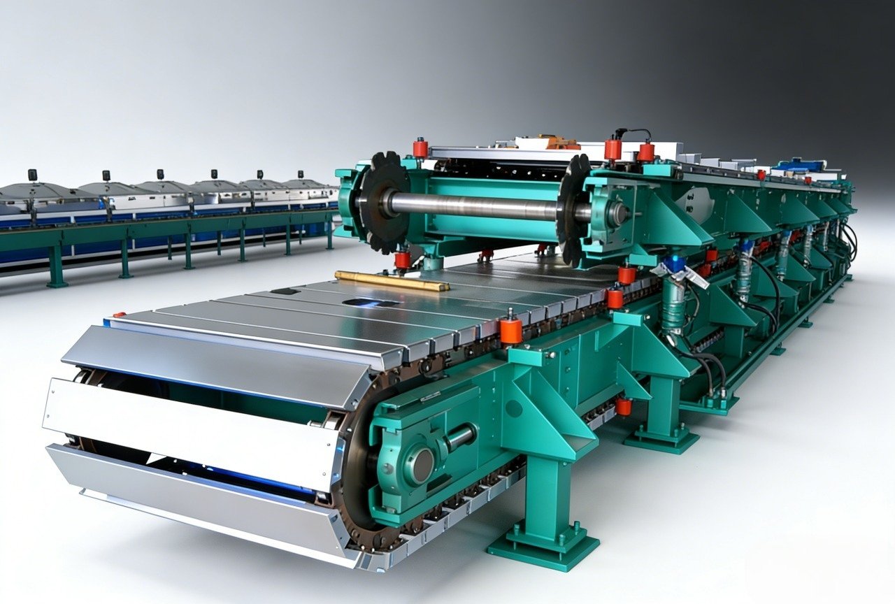
Electrical tracing is the common choice for smaller bore runs: it is easy to zone and to control by surface temperature. A fluid jacket gives more even heat and suits long headers and manifolds, but it adds a second fluid system with its own pressure, leak risk and maintenance. Whichever you choose, control on surface temperature as well as fluid temperature, and interlock the heat so a stopped line cannot sit at a hot setpoint indefinitely.
Isocyanate service needs particular care. The material can crystallize when a section cools toward its solidification range, and the crystals do not disappear when flow restarts. Insulate valves, filters and flanges, not just straight pipe, because those items create the cold spots that start the problem.
Expansion is part of the same package. A traced and insulated line moves more than an uninsulated one, so supports and anchors have to allow for it without creating low points that trap material.
Verify at start-up. Record surface temperature at several points along each component line, at the filter body and at the head inlet, then set alarm limits from the recorded values rather than from the design assumption.
Materials, Joints and Pre-Commissioning Checks
Material selection follows the chemistry and the contamination risk. Stainless steel is the usual choice for isocyanate and for any line where colour or clarity matters, because it resists corrosion and cleans predictably. Carbon steel can serve some polyol duties, but mill scale and rust have to be removed before commissioning. Avoid copper and brass in isocyanate service, and check gasket compatibility with the specific component rather than with the family name.
Joint strategy matters as much as the alloy. Welded or flanged joints reduce the number of places where material can sit, and they remove a common failure: fragments of thread tape travelling downstream into a filter or a mixing head. Where threads are unavoidable, use a sealant compatible with the component and apply it sparingly.
Run the pre-commissioning work in order:
- Compare the as-built isometric against the sizing sheet: bore, length, fittings, tracing circuits and insulation.
- Confirm every component line has a gauge at the head inlet.
- Check that no line has a low point without a drain and no branch without flow.
- Pressure test with a medium that is compatible with the component. Do not water-test isocyanate lines; use dry nitrogen or air, or a compatible fluid agreed with the material supplier.
- Verify tracing and insulation with temperature readings, not with drawings.
- Run a recirculation test and record velocity in the return leg.
- Verify ratio by weight check against the machine setpoint at production flow, not at idle.
Calibration confirms the pump; it does not confirm the run between the pump and the head, so the two checks belong in the same commissioning record. <PU Foam Injection Machine: Key Components & Calibration Best Practices> covers key components and calibration practice for PU foam injection machines.
What to Send With a Piping Enquiry
Piping decisions move faster when the numbers arrive together. Send the component flows at operating temperature, the mixing ratio and the unit it is controlled in, viscosity and density at line temperature, the velocity you intend to hold, the equivalent length and fitting count, the pressure available at the pump outlet, the pressure the mixing head needs, the suction static head, the tracing type and setpoint, and the ambient conditions in the plant. With that list, a bore and a pressure budget can be checked against the machine instead of guessed from the pump outlet size.
Haifeng Polyurethane Machinery builds metering and foaming packages around these figures, including non-standard layouts where the run to the head is fixed by the building. Send the list to info@haifeng-automation.cn or WhatsApp 86 13566296633, and we will review the line against the machine specification before any pipe is ordered.
FAQ
Should the polyol and isocyanate lines be the same diameter?
No. Each line is sized from its own flow and target velocity, and the flows differ by the mixing ratio. Equal bores on unequal flows produce unequal velocities, unequal residence times and unequal pressure loss. What should match, as closely as the layout allows, is the pressure at the two head inlets at steady flow. Matching the bore is a convenience on the drawing, not a design principle.
What pipe size handles 10 liters per minute of filled polyol?
At 0.6 m/s, 10 L/min needs about 18.8 mm, so DN 20 is the minimum and DN 25 is common once pressure drop and layout are counted. Filled material adds two checks: whether the resulting velocity keeps filler moving in horizontal runs, and whether the pressure budget survives at working viscosity. The bore follows the velocity you can defend, not the size of the pump outlet.
Can flexible hose replace rigid pipe between the metering unit and the head?
Short flexible sections at the head are normal and useful. Long hose runs are a different matter: the bore printed on the hose may not match its true bore under pressure, the liner must suit both components, and the pressure rating falls as temperature rises. Hose also adds volume and can create a low point. Keep flexible sections short and support them.
How do I stop isocyanate from crystallizing inside the line?
Temperature and movement. Trace and insulate the full run, including valves, filters and flanges, keep recirculation running through production and breaks, and remove stagnant branches. Bring a cold line up to temperature before restoring flow. Where a shutdown is long, a documented flush or full drain is safer than leaving material sitting in an insulated pipe at the wrong temperature.
Do I need recirculation on both components?
Usually yes where temperature control and filler suspension matter, because a stagnant line loses heat and lets solids settle. The cost is real: extra heat load, additional shear and a return line that must be sized like a supply line. Some plants recirculate isocyanate only and rely on insulation for polyol, which works when runs are short and the polyol is unfilled. Measure the return velocity before deciding.
References
[1] ISO 6708:1995, “Pipework components — Definition and selection of DN (nominal size),” ISO, 1995.
If you’re interested, check out these related articles:
How to Start a PU Safety Shoe Manufacturing Business
Cost of a Tire Foam Filling Machine