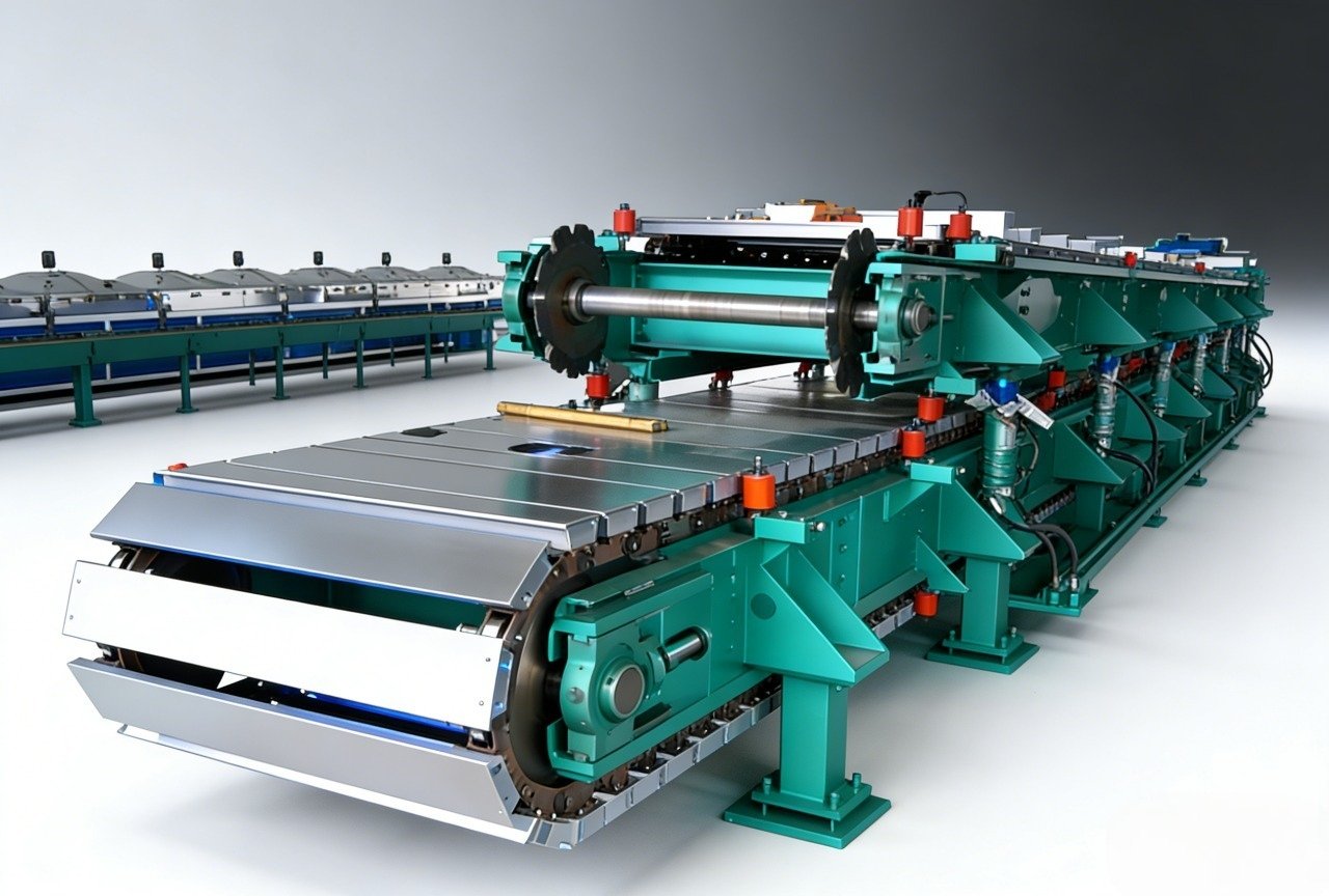
Production teams that thermoform semi-rigid polyurethane blanks rarely fail because the chemistry is wrong. They fail because the box-foaming cell was specified like a generic foam machine: the metering pump was sized for average output instead of the pour window, the mixing head produced the wrong cell structure, and the block was poured too cold or too fast. The result is density variation from block to block, surface voids, or scorched cores that are discovered only after slitting.
This guide explains what box-foaming equipment for semi-rigid automotive thermoforming foam actually needs to do, where batch box foaming fits, which subsystems control quality, and what to lock before you issue a quotation.
What Semi-Rigid Thermoforming Foam Actually Requires
Automotive thermoforming foam is not flexible slabstock and not rigid insulation. It is a semi-rigid, usually open-cell or partially open-cell block that is slit into sheets, heated, and formed into headliners, door-panel carriers, dash insulators, parcel shelves, and NVH mats. Apparent density is normally measured to ISO 845 [1]; compression stress-strain behavior is tested to ISO 3386-1 [2], while compression set and other durability checks follow ASTM D3574 [3]. Because these materials end up inside the cabin, flammability is commonly evaluated to FMVSS 302 [4] or ISO 3795 [5].
When tested to ISO 845 [1], automotive semi-rigid grades commonly sit between roughly 40 and 80 kg/m³ in apparent density, but the exact number is set by the thermoforming part, not by the machine. This profile matters for equipment selection because it sets cream time, exotherm, and how much nucleation the mixing head must provide. A formulation that rises too fast in a deep box can trap gas; one that rises too slowly can leave density bands near the bottom.
Before the layout is fixed, send block size, target density and weekly volume to info@haifeng-automation.cn or WhatsApp +86 135 6629 6633. This is the lowest-cost stage to confirm metering and mold-handling requirements.
Box Foaming vs Continuous Slabstock
Batch box foaming makes sense when weekly output is moderate, block dimensions are large enough to need individual exotherm management, or the plant changes density and hardness often. It uses an open-top box or mold, a metering unit, and a traversing mixing head. Continuous slabstock wins for high-volume flexible foam with long campaigns and fewer changeovers.
For semi-rigid automotive blanks, box foaming is often the safer starting point because it matches short campaigns and thicker blocks. It also allows slower, more controlled rise without the complexity of a moving conveyor and side-paper system. The trade-off is that every block becomes its own process event: pour pattern, temperature, and demold timing must be repeated consistently.
Box-foam and slabstock lines share a metering and mixing core, but batch layout changes exotherm and material-change behavior. <Polyurethane Foam Machines: Types, Principles & Applications> covers the base machine classes before you split batch and continuous layouts.
The Equipment Chain That Determines Foam Quality
Four subsystems determine whether a semi-rigid block comes out usable: metering, mixing, laydown, and thermal environment.
Metering and Ratio Control
The polyol and isocyanate components must be delivered at the target ratio at every point in the pour. A closed-loop servo metering system that compares commanded and actual flow is preferred because it corrects drift during the shot instead of only between batches. A metering deviation of half a percentage point can move density enough to fail a thermoforming blank, especially when the block is later slit into thin sheets.
Mixing Head
For box foaming, high-shear dynamic mixing is often used because it controls nucleation and gives fine, uniform cells in semi-rigid formulations. Static mixers work for narrower viscosity windows but can struggle with filled or high-viscosity systems. The key is not simply “good mixing” as a label; it is repeatable mixing at the start and end of every pour, when flow rate is lowest.
Pour Pattern and Traverse
Pour pattern must match box geometry. Poor laydown traps air and creates density bands. The head should follow a programmable pattern, typically perimeter first and center serpentine, with traverse speed tied to flow rate. If the head slows or pauses, the local shot mass increases and the density profile changes.
Box and Mold Handling
Box support, vents, release, and lifting are part of foam quality. A box that flexes as the foam rises changes the block profile. Vents must be placed so that rising gas escapes without allowing foam to break through and form surface channels.
Raw Material Conditioning
Temperature control of day tanks and recirculation keeps viscosity stable and protects against ratio drift. Moisture ingress in polyol or isocyanate systems creates carbon dioxide or side reactions that change cell structure. Conditioning is not a utility detail; it is a process parameter.
One box-foaming machine configuration designed for this job, the Haifeng HF-LPM-1A1B-LO, pairs dual vacuum degassing with a servo closed-loop metering system and synchronous box sequencing. The point is not the brand; the point is the architecture: vacuum defoaming, closed-loop ratio control, and synchronized traverse.
What to Lock in the Quotation
Before requesting pricing, fix the following parameters. A quotation based on “one foam machine” rather than these inputs will almost certainly be mis-sized.
| Parameter | What to Specify | Why It Matters |
|---|---|---|
| Block dimensions | Length × width × height, plus slitting allowance | Sets box size, pour volume and traverse stroke |
| Target density | kg/m³ tested to ISO 845 [1] | Sets shot weight and metering precision |
| Hardness or CLD | Stress-strain target to ISO 3386-1 [2] | Influences formulation and cell structure |
| Materials | Viscosity, filler content, pot life | Determines pump, mixer and temperature-control design |
| Output | kg per pour or blocks per day | Sizes pumps without overbuying |
| Changeover frequency | Batch count between formula changes | Determines cleaning and flush system |
| Data traceability | Recipe, flow, pressures, temperatures | Supports acceptance tests and defect review |
If the top of the table is not available, begin with block dimensions and target density. Those two numbers eliminate the largest class of wrong-machine decisions.
To avoid locking the wrong output range, route the completed parameter list to info@haifeng-automation.cn or WhatsApp +86 135 6629 6633 for a box-foaming machine selection review.
Capacity and Layout for a Box-Foaming Cell
Daily foam output can be calculated directly:
Daily output (kg/day) = block volume (m³) × block density (kg/m³) × blocks per day
For example, a 2.0 m × 1.5 m × 1.0 m block has a volume of 3.0 m³. At 60 kg/m³, that is 180 kg of foam per block. Ten such blocks per day is 1,800 kg/day. This is an example calculation, not a universal target; adjust it to your actual block and density.
The next check is pour time. The full shot should be delivered within the usable pour window, which is always shorter than the cream time. If the machine is sized only for average daily output, it may be too slow to complete a large shot before viscosity rise creates flow lines and density variation. Size the output range for the largest block, not the average block.
Build curing and storage into the layout. Semi-rigid blocks need staged cooling and typically at least 24 hours before slitting, longer for thick blocks. A packed storage area next to the foaming cell is not extra floor space; it is part of the process. Site utilities should include stable power and compressed air in the 0.8–1.0 MPa range, sized for continuous operation rather than peak-nameplate duty.
Defects That Trace Back to the Equipment
Most box-foam defects are blamed on formulation first, but the equipment causes are just as common and easier to confirm.
Density Variation From Block to Block
Density variation usually means ratio drift, temperature fluctuation, or a calibration interval that is too long. A machine that holds ratio on a test shot is not the same as one that holds ratio through a 10-hour production day. Closed-loop flow monitoring and recirculation pressure control address this directly.
Surface Voids and Trapped Air
Voids near the top surface often come from gas entrainment in the pour or from a pour pattern that traps air against the box wall. Vacuum degassing and a controlled laydown pattern reduce the gas load, but only if the metering system does not pull air through a leaking suction line.
Scorched Core or Discolored Bands
Thick semi-rigid blocks generate meaningful exotherm. If the core stays hot too long, oxidation discolors the foam and degrades mechanical properties. This is controlled by block thickness, pour temperature, storage airflow, and demold timing. The machine cannot solve an undersized cooling area.
Collapse or Coarse Cells
Late pour, weak mixing, or incorrect catalyst blending can cause large irregular cells or partial collapse. When the same formulation runs well in a lab mixer but poorly on the line, the usual suspects are mixing-head shear, flow-rate turndown, and temperature difference between A and B.
Box-foaming equipment runs in a reactive environment; maintenance intervals are not optional. <PU Low Pressure Foaming Machine: Maintenance Checklist & Troubleshooting Guide> covers checklist items that prevent most density and mixing faults.
Talk to a Box-Foaming Applications Engineer
The fastest way to specify the correct box-foaming cell is to share the process boundary, not just the machine budget.
Send the following to info@haifeng-automation.cn or WhatsApp +86 135 6629 6633:
- Block dimensions and target density
- Required daily or weekly output
- Formulation type, viscosity and filler content
- Cream time, gel time and cure time
- Utility voltages and compressed-air availability
- Existing building dimensions or layout constraints
An applications engineer can then return a metering, mixing and traverse recommendation based on the box geometry rather than a generic machine quote.
Frequently Asked Questions
What density range is typical for semi-rigid automotive thermoforming foam?
The range depends on the part, but automotive semi-rigid grades commonly fall between about 40 and 80 kg/m³ when measured to ISO 845 [1]. The target should come from the thermoformed part specification, not from the machine supplier.
Can a standard flexible slabstock machine be used for box-foamed semi-rigid foam?
In most cases, no. The pour window, mixing-head nucleation, exotherm management and mold handling are different enough that a slabstock line adapted to boxes usually creates density variation and changeover problems. A dedicated box-foaming cell is the more reliable route.
How does box foaming compare with continuous slabstock for short runs?
Box foaming is generally better for short runs, frequent density changes and thick blocks. Continuous slabstock becomes more economical when one formulation runs for many hours and block thickness is limited.
What metering accuracy should be specified?
For semi-rigid automotive foam, closed-loop ratio control with flow feedback is more important than a single accuracy number. The specification should require stable ratio across the full output range, not only at one test point.
Why is core temperature control more important in thick box foam?
Thick blocks retain exothermic heat. If the core temperature stays high too long, the foam can scorch, discolor or lose mechanical properties. Cooling, storage airflow and demold timing are part of the process design.
What data should I prepare before requesting a quotation?
At minimum, prepare block dimensions, target density, weekly output, material viscosity and filler content. Cream time, gel time and utility availability should follow. These inputs determine metering output, mixing-head type, traverse stroke and temperature-control sizing.
References
[1] ISO 845:2009, Cellular plastics and rubbers — Determination of apparent density, International Organization for Standardization, Geneva, Switzerland, 2009.
[2] ISO 3386-1:1986, Polymeric materials, cellular flexible — Determination of stress-strain characteristics in compression — Part 1: Low-density materials, International Organization for Standardization, Geneva, Switzerland, 1986.
[3] ASTM D3574-17, Standard Test Methods for Flexible Cellular Materials—Slab, Bonded, and Molded Urethane Foams, ASTM International, West Conshohocken, PA, 2017.
[4] U.S. Department of Transportation, Federal Motor Vehicle Safety Standard No. 302, Flammability of Interior Materials, 49 CFR 571.302, Washington, DC.
[5] ISO 3795:1989, Road vehicles, and tractors and machinery for agriculture and forestry — Determination of burning behaviour of interior materials, International Organization for Standardization, Geneva, Switzerland, 1989.
If you’re interested, check out these related articles:
How Long Do Foam Filled Tires Last
How to Fill Foam in Heavy Duty Tires