Most output-range mistakes on low-pressure PU foaming machines do not appear at the quoting stage. They appear six months later, when a plant tries to run two different products on the same line: one large shot that pulls the maximum flow rate, and one small shot that forces the pumps to run at the bottom of their range. The result is usually the same — ratio drift on the small part, cavitation on the large one, and a machine that can no longer hold the component ratio the specification promised.
The problem is rarely the pump itself. It is the way the output range was specified. A machine rated for 5–50 g/s can meter precisely at 20 g/s but may struggle below 5 g/s. A “50 g/s maximum” figure may only be achievable at low material viscosity, at a specific pump speed, and with the temperature exactly at setpoint. If the sizing calculation ignores turndown, viscosity correction, or the difference between total output and component flow rate, the selected machine will underperform in exactly the situation the plant bought it to handle.
Why Output Range Sizing Goes Wrong
Three errors repeat across most undersized and oversized low-pressure stations.
The first mistake is sizing from total output alone. Total output is what the parts require, but the machine meters two or more components individually. A 100:50 ratio at 10 kg/min total means one pump must deliver about 6.7 kg/min and the other about 3.3 kg/min. If the smaller pump cannot run stably at 3.3 kg/min, the larger pump’s capability is irrelevant.
The second mistake is accepting a wide range without checking the low end. Machine builders often quote the maximum output as the headline number. The minimum stable output is the figure that determines whether the machine can handle small parts, short pours, or prototyping work without ratio drift.
The third mistake is treating viscosity as a constant. Polyol, isocyanate, and filled systems change viscosity with temperature and filler loading. A pump’s effective capacity drops as viscosity rises, so the same pump that delivers 20 kg/min of a thin polyol may deliver only 14 kg/min of a filled system at a lower temperature. The output range shrinks in real operation, and the sizing must account for that shrinkage.
Step 1: Calculate Total Output from Shot Weight and Pour Time
The correct starting number is not the machine’s maximum capacity. It is the flow rate the process actually requires.
For discontinuous pouring, the calculation is simple:
Total output (g/s) = shot weight (g) ÷ pour time (s)
Shot weight comes from part volume and final foam density. A 250 cm³ polyurethane sole at 0.55 g/cm³ density needs approximately 137.5 g of material. Add an 8% waste factor for mixing-head residue, purging, and flashing, and the shot weight becomes roughly 150 g.
If the mold station allows an 8-second pour before the material’s pot life creates flow lines or fill defects, the total required output is 150 ÷ 8 = 18.75 g/s, or about 1.13 kg/min.
The metering accuracy standard for this type of equipment is typically ±0.5% on component flow, as specified in China’s polyurethane pouring machine industry standard [1]. A deviation of one percentage point in the component ratio can shift final foam density by more than 3 kg/m³. That is why the output range cannot be a loose estimate: the pumps must hold the calculated flow inside a narrow error band for the entire pour.
Getting the shot weight wrong has direct scrap consequences. <Polyurethane Foam Machine Types: The Scrap Cost of Inaccurate Metering> covers how metering errors convert into batch-level material loss and density variation.
Step 2: Split Total Output into Component Flow Rates
Once total output is known, it must be split into the individual component streams according to the mixing ratio.
For a ratio expressed as A : B (for example polyol : isocyanate = 100 : 50), the component fractions are:
Q_A = Q_total × [A ÷ (A + B)]
Q_B = Q_total × [B ÷ (A + B)]
At 1.13 kg/min total output and a 100:50 ratio:
- Polyol flow = 1.13 × (100 ÷ 150) = 0.75 kg/min
- Isocyanate flow = 1.13 × (50 ÷ 150) = 0.38 kg/min
These two numbers, not the combined figure, define the pump sizes. Each pump must reach its required flow comfortably and hold it without hunting.
Mixing uniformity is constrained by the same math. The mixing head must achieve at least 99.5% uniformity under these component flows to prevent soft streaks and hardness variation in the finished part, a requirement aligned with ASTM D3795 test practice for pourable rigid polyurethane foam systems [2].
Step 3: Build a Safe Operating Window
The calculated flow is a single point, not an operating range. Machines need a window that covers the largest part, the smallest part, and future variation in between.
A practical method is to apply a safety factor to the calculated maximum flow. For most low-pressure PU stations, a factor of 1.2 to 1.3 is sufficient. It accounts for viscosity variation, raw-material batch differences, pump wear over time, and the occasional need to run a slightly larger part.
Using the example above, a 1.13 kg/min calculated flow becomes a target maximum of:
1.13 × 1.3 ≈ 1.5 kg/min
The machine should be specified to hold the metering accuracy across a continuous operating range, not just at one point. A pump that only meets accuracy at its optimal speed is not a production tool; it is a laboratory fixture. The operating window must include every pour time and shot size the line will actually run.
Step 4: Verify Minimum Stable Flow and Turndown
Maximum output gets the attention. Minimum stable flow determines whether the machine can run small parts at all.
Every positive-displacement metering pump has a practical lower limit. Below that limit, leakage across the pump clearances becomes a larger fraction of the displaced volume, and the flow becomes discontinuous rather than smooth. For gear pumps in this application, the usable turndown ratio is often around 10:1, though the exact figure depends on pump clearances, material viscosity, and component temperature.
If the specified maximum is 1.5 kg/min, a 10:1 turndown means the minimum stable flow is roughly 0.15 kg/min. That is fine for the example line because the smallest anticipated shot — say 50 g poured in 8 seconds, or 0.375 kg/min — sits above the floor. The machine can handle it without dropping into the unstable zone.
But if the plant also wants to run a small prototype at 20 g in 8 seconds (0.15 kg/min), the machine is operating right at the limit. That is not a safe margin. In that case the sizing must either raise the minimum stable capability or accept that prototyping needs a separate, smaller station.
Turndown is often invisible in a brochure. <Polyurethane Machinery 101: A Comprehensive Guide to Equipment Types and Engineering Selection> covers pump types, metering principles, and how to read equipment specifications without overbuying or oversizing.
Step 5: Correct for Viscosity, Fillers, Day Tanks and Feed Circuits
Viscosity changes everything. A standard polyol might be 400–800 mPa·s at 25°C, while a filled polyol with pigment or flame retardant can exceed 3,000 mPa·s. The isocyanate component is usually lower in viscosity, often below 200 mPa·s for MDI-based systems, but it is also more sensitive to moisture and temperature. Material TDS data, including viscosity at processing temperature and isocyanate content, is the starting point for pump and piping selection [3].
Higher viscosity reduces the effective output of a pump at a given speed. It also increases inlet pressure drop, which raises the risk of cavitation. The fix is not always a larger pump; it may be a larger inlet line, a preheating jacket, or a different pump geometry. But the sizing calculation must assume the highest viscosity the material will realistically reach at the lowest processing temperature.
Day tank sizing follows the same logic. A tank that feeds a 1.5 kg/min peak flow must hold enough material to run for at least a few hours without refill, plus enough dead volume to keep the recirculation loop primed. For a two-hour buffer at maximum throughput, the polyol tank in the example would need roughly 90 kg of usable capacity for that component, and the isocyanate tank about 45 kg — before adding recirculation volume and level-sensor dead zones.
The relationship between material characteristics and machine design is not always obvious. <Polyurethane Foam Machines: Types, Principles & Applications> covers the interaction between raw-material properties, metering hardware, and mixing-head behavior.
Worked Example: Sizing a Shoe-Sole Pouring Station
Here is the complete calculation for a single-station low-pressure line producing a PU shoe sole.
Given:
Part volume = 250 cm³
Final foam density = 0.55 g/cm³
Waste factor = 8%
Pour time = 8 s
Mixing ratio (polyol : isocyanate) = 100 : 50
Safety factor = 1.3
Turndown required = 10:1
Step 1 — Shot weight:
250 × 0.55 = 137.5 g
137.5 × 1.08 = 148.5 g, round to 150 g
Step 2 — Total output:
150 g ÷ 8 s = 18.75 g/s
18.75 × 60 ÷ 1000 = 1.13 kg/min
Step 3 — Maximum output with safety factor:
1.13 × 1.3 = 1.5 kg/min
Step 4 — Component flow rates at maximum:
Polyol = 1.5 × (100 ÷ 150) = 1.0 kg/min
Isocyanate = 1.5 × (50 ÷ 150) = 0.5 kg/min
Step 5 — Minimum stable flow check:
1.5 kg/min ÷ 10 = 0.15 kg/min
Smallest anticipated shot: 50 g in 8 s = 0.375 kg/min
Result: 0.375 > 0.15, so the machine has comfortable margin at the low end.
Step 6 — Day tank sizing for the polyol component:
At 1.0 kg/min peak, a two-hour buffer requires:
1.0 × 120 = 120 kg usable polyol capacity
Plus recirculation volume and sensor dead zones, the installed tank should be rated at least 150 kg.
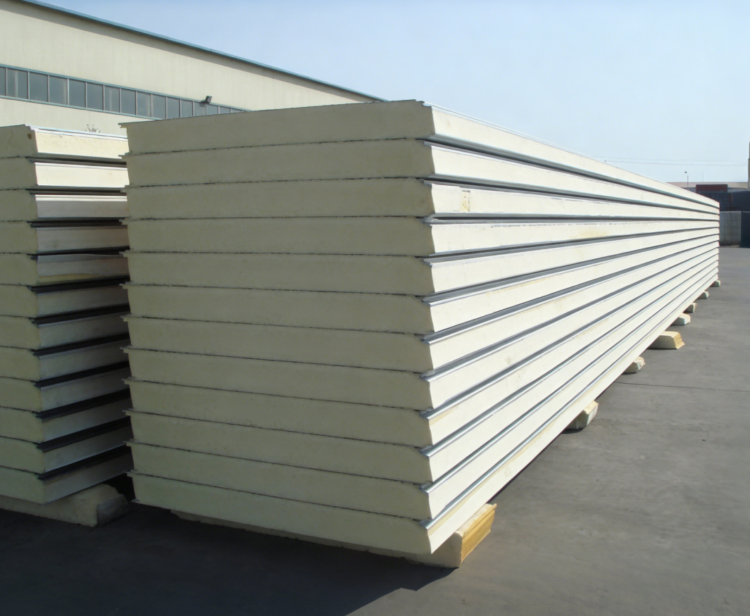
This example gives a defensible, repeatable sizing. The same method works for gaskets, steering-wheel foam, vibration dampers, or any discontinuous PU part. The numbers change; the logic does not.
Need to verify your numbers against a real machine spec? Send your shot weight, pour time, mixing ratio, and material viscosity to info@haifeng-automation.cn with “sizing check” in the subject line. An applications engineer will confirm whether your calculated operating window fits an available metering configuration before you commit to a pump size.
Get Your Sizing Checked Before You Buy
A low-pressure PU machine is much easier to adjust before it is installed than after. If you are specifying a new line or rechecking an existing one, send the following to our engineering team:
- Part weight, density, and mold volume for the smallest and largest parts you plan to run
- Pour time or cycle time per station
- Mixing ratio and material viscosity at processing temperature
- Whether the materials contain fillers, pigments, or abrasive additives
- Line configuration: number of pouring stations, conveyor speed, and robot integration if any
- Minimum and maximum shot sizes across all planned products
Reach us at info@haifeng-automation.cn or WhatsApp 86 13566296633.
Frequently Asked Questions
What is the minimum stable output of a low-pressure PU foaming machine?
It depends on the pump type, clearances, material viscosity, and temperature. For many gear-pump systems, the practical lower limit is roughly 10% of the rated maximum output, giving a turndown ratio of about 10:1. Below that floor, metering accuracy degrades because pump leakage becomes a significant fraction of the displaced volume.
How do I convert total output into polyol and isocyanate flow rates?
Divide the total flow according to the ratio fractions. For a ratio of A:B, use Q_A = Q_total × [A ÷ (A + B)] and Q_B = Q_total × [B ÷ (A + B)]. A 100:50 ratio at 1.5 kg/min gives 1.0 kg/min for the first component and 0.5 kg/min for the second.
Does viscosity change the effective output range?
Yes. Higher viscosity reduces pump capacity at a given speed and increases inlet pressure drop, which raises the risk of cavitation. The output range should be calculated at the highest expected viscosity and the lowest expected processing temperature, not at ideal laboratory conditions.
How much safety factor should I apply to maximum output?
For most low-pressure PU stations, a factor of 1.2 to 1.3 is appropriate. This covers material batch variation, pump wear, temperature swings, and the occasional need to run a slightly larger part. A larger factor can hide an oversizing problem and force the machine to run too low on the range for normal work.
Can one low-pressure machine handle both prototyping and full production output?
It depends on the turndown ratio. If the smallest prototyping shot requires a flow below the machine’s minimum stable output, the machine will drift on ratio and pour weight. In that case, either specify a machine with a wider usable turndown or keep a separate smaller station for prototyping.
References
[1] China Machinery Industry Standard, “Polyurethane Pouring Machine,” Zhejiang Haifeng Automation Equipment Co., Ltd., Beijing, China.
[2] ASTM D3795, “Standard Test Method for Thermal Flow, Cure, and Behavior Properties of Pourable Rigid Polyurethane Foam Systems,” ASTM International, West Conshohocken, PA, USA.
[3] ISO 14896:2009, “Plastics — Polyurethane raw materials — Determination of isocyanate content,” International Organization for Standardization, Geneva, Switzerland.
If you’re interested, check out these related articles:
PU Rain Boot Production Line Cost
Rain Boot Manufacturing Equipment List
High Pressure vs. Low Pressure Polyurethane Foam Machine: How to Choose the Right One for Your Production
Cost of a Tire Foam Filling Machine