



When you specify utilities for polyurethane processing equipment, the expensive mistakes usually sit at the interface, not inside the machine. A metering unit can hold its published ratio while the plant supplies wet air, low cooling-water pressure, or an exhaust duct that was sized before the enclosure was fixed. The useful approach is to define a simultaneous utility envelope at the machine battery limit: flow, pressure, temperature, quality, and responsibility at the same operating condition. That schedule can be quoted, checked, and accepted. It also gives the machine builder a clear basis for the utility table instead of a list of vague site assumptions.
What Utilities Does Polyurethane Processing Equipment Really Need
Polyurethane processing covers low-pressure foaming, high-pressure impingement, elastomer casting, spray, and composite processes. The utility list changes with the process, but the categories are consistent. The machine needs electrical power, compressed air, cooling or heating fluid, exhaust, and a control network. Some machines also need hydraulic power, nitrogen, chilled water, or solvent cleaning. The utility schedule should describe conditions at the battery limit, the point where the plant service connects to the machine scope.
| Utility | What to put in the schedule | Why the machine cares |
|---|---|---|
| Electrical power | Voltage, frequency, phase count, continuous kVA, starting current, harmonic limit, earthing arrangement | Heaters, drives, and controls respond to voltage drop and unbalance; the wrong earthing blocks safe isolation |
| Compressed air | Flow at the machine inlet, pressure under that flow, dew point, particulate class, oil class | Valves, cylinders, and purge points respond to wet or dirty air; a static pressure reading hides a flow problem |
| Cooling water | Supply and return temperature, allowable temperature rise, pressure at inlet, allowable pressure drop, water quality | Heat exchangers, hydraulic oil, and mixing heads lose control when flow or temperature drifts |
| Heat transfer fluid | Fluid type, supply and return temperature, heat load, expansion volume, pump curve | Day tanks, hoses, and metering pumps depend on stable viscosity and temperature |
| Exhaust and make-up air | Capture points, hood face velocity, duct static pressure, discharge location, make-up air balance | Operator exposure and stable room pressure depend on capture at the source, not general dilution |
| Control and data | Protocol, IP rating, UPS duration, network segregation, data retention | PLC, HMI, remote service, and traceability depend on a supply that survives normal plant disturbances |
A line that lists only air pressure and water temperature is not a specification. The machine responds to pressure at flow, dew point, water pressure drop, and voltage balance. Put those conditions in the schedule and tie each one to a tag on the P&ID.

Why the Nameplate Load Is the Wrong Sizing Basis
Nameplate values describe component limits. They do not describe what the plant will see at the same moment. A PU line has heat-up, production, mold cleaning, and standby. The highest electrical demand may occur during heat-up, while the highest cooling load may occur during production. The highest air demand may occur at cleaning, when the mixing head is open and several valves cycle together.
Define the utility envelope as the set of simultaneous minimum and maximum conditions the plant guarantees at the battery limit for each operating mode. This is a better basis than adding every connected load. Ask the builder for a load profile with time, duration, coincident users, and duty cycle. Ask which loads can run at the same time and which are interlocked.
Oversizing has a cost. An oversized chilled-water system may run at low load and short-cycle the chiller; a header that is too large can make flow measurement unreliable. Undersizing has a different cost: temperature drift, slow heat-up, and nuisance trips. The right size is the smallest system that holds the envelope with the agreed redundancy.
Machine architecture and utility demand are easier to compare when the pump, mixing head, and control concept are already fixed. <The Ultimate Guide to Low-Pressure Foaming Machines for PU Elastomers> covers low-pressure foaming machine selection and process setup for PU elastomers.

How Should You Specify Electrical Power and Control Supply
Start with the site, not the machine. Record the actual voltage, frequency, phase count, earthing system, and available short-circuit capacity. IEC 60038 lists standard voltages, but the nameplate rating and a site measurement govern the connection [1]. A machine marked for one voltage may not tolerate the site’s full tolerance band without a transformer.
Specify continuous kVA, maximum demand, starting current, voltage tolerance, phase unbalance, and harmonic limit at the point of common coupling. Variable-frequency drives and heater controls can distort the supply. Ask for the machine’s harmonic data and do not assume a built-in filter corrects plant harmonics.
Control power should be separated from power circuits. Define the 24 V DC supply, UPS duration for PLC and HMI, emergency-stop category, and service outlets. Electrical equipment for machines should be specified to IEC 60204-1 [2]. Enclosure protection should be selected to IEC 60529 [3] for the cleaning method.
Check the details that cause callbacks: terminal torque, insulation resistance, phase rotation, cable gland size, segregation of power and signal cables, and equipotential bonding. A clean power log at startup is more useful than a certificate that lists only the nominal voltage.
What Air and Hydraulic Quality Should the Utility Schedule Fix
Compressed air is a controlled utility, not a shop service. Specify flow at the machine inlet, pressure under that flow, and purity class. ISO 8573-1 defines classes for particles, water, and oil [4]. A dryer that works at the compressor can still leave the machine with wet air if the receiver is in a cold spot or the filter is loaded.
State the air quality at the machine, not at the compressor outlet. If air can contact polyurethane material through a purge or blow-off, treat contamination as a process risk, not only a valve risk. Size the receiver for peak demand, but do not use a receiver to fix an undersized compressor.
Hydraulic systems need their own schedule. State fluid type, viscosity grade, cleanliness code, filtration, reservoir temperature, pressure, and flow. ISO 4406 codes solid-particle contamination [5]. Pressure alone proves little: a power pack can show pressure at deadhead and still stall when a cylinder moves.
Check gauge location, accumulator precharge, relief-valve setting, oil cooler, and return-line filtration. These details decide whether a cast PU machine holds pressure during the pour or drifts when the pump loads.
Air quality and hydraulic stability belong to the same production setup, not to separate building services. <High Pressure PU Foaming Machine for Car Seats & Steering Wheels: A Production Setup Guide> covers the production setup for high-pressure PU foaming of car seats and steering wheels.
How Do You Size Cooling Water and Temperature Control
Cooling load is not the same as connected motor power. Heat arrives from hydraulic oil, pump inefficiency, heater leakage, hot material, and the exothermic reaction around the mold. The machine-side heat exchanger sees only part of that load. Ask the builder for heat rejection at each operating mode and for the allowable supply and return temperatures.
The cooling flow is set by heat rejection divided by the product of fluid specific heat and allowable temperature rise. A chiller’s leaving-water temperature does not guarantee the temperature at the machine inlet. Pipe length, fittings, a partly closed valve, and a fouled heat exchanger all change the result.
Specify supply temperature, return temperature, allowable temperature rise, pressure at inlet, allowable pressure drop, water quality, and cleaning access. State glycol concentration if freeze protection is used, because it changes heat capacity and viscosity. For temperature-control units, specify heating capacity, cooling capacity, pump curve, fluid, and safety limits.
At commissioning, log flow, supply temperature, return temperature, and pressure drop at stable production. A rising temperature difference with falling flow points to fouling or a restriction. A falling difference with high flow may point to a bypass or a sensor error. Neither reading is useful without the operating mode recorded beside it.
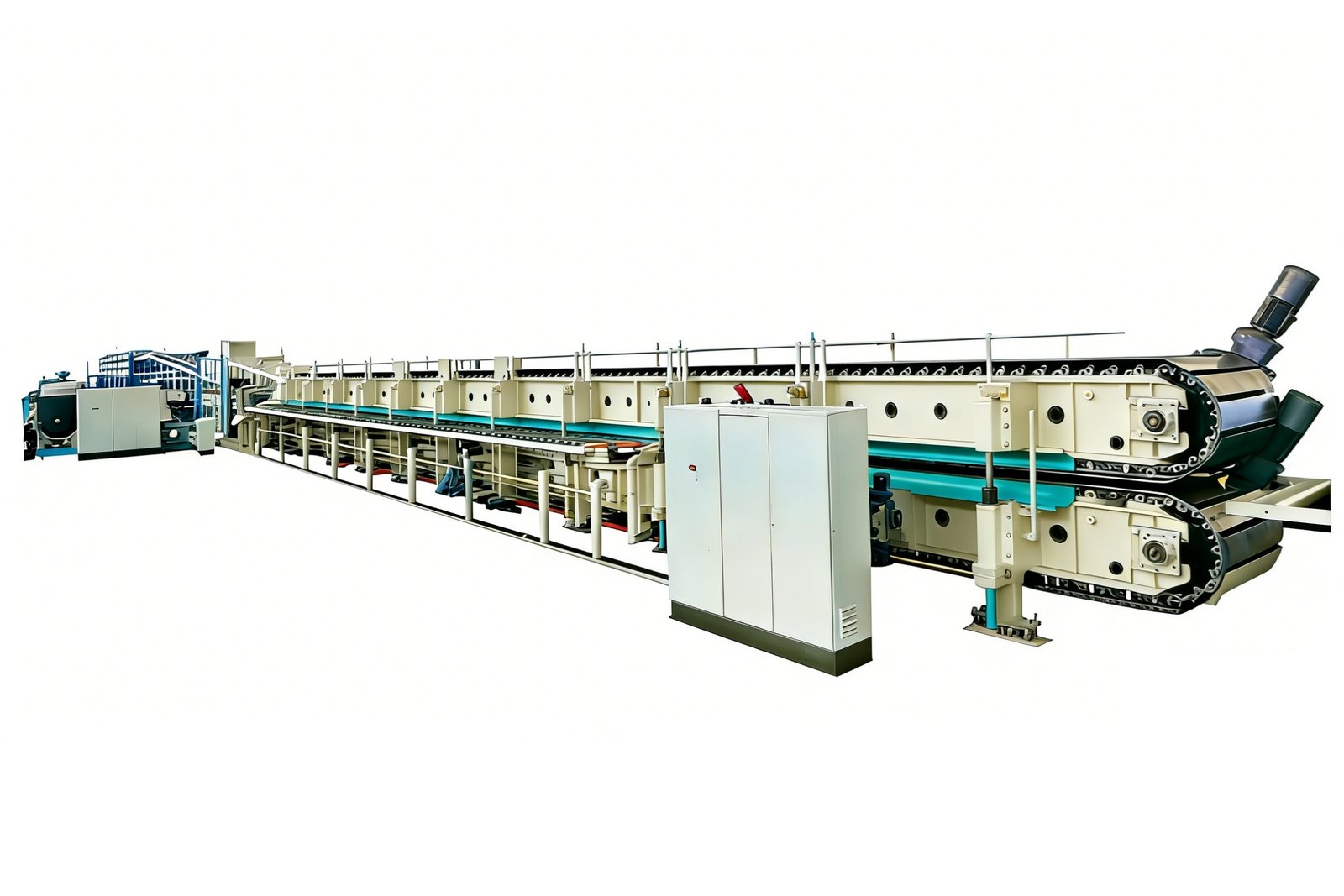
A continuous foam line concentrates many utility loads in one enclosure, so cooling and exhaust have to be read as a system. <Inside a Continuous PU Foam Line: Foam Production> covers how a continuous PU foam line is arranged and operated.

Which Ventilation and Exhaust Conditions Belong in the Specification
Polyurethane processing can release isocyanate vapor, amine catalysts, blowing agents, and solvent from cleaning. General room ventilation dilutes the air, but it does not capture vapor at the source. The schedule should identify capture points at the mixing head, open pour, mold opening, cleaning station, and raw-material storage.
Specify hood face velocity, capture airflow, duct static pressure, discharge location, make-up air, and the material of the duct. A hood that looks large can still have a dead zone at the operator’s breathing line. Test with smoke at the actual pour position, not at the center of the hood.
Do not recirculate exhaust unless the filtration and monitoring are approved for the chemicals in use. Make-up air must be conditioned and balanced. Adding exhaust without make-up air creates negative pressure, which can starve combustion equipment, pull doors, and change airflow at other hoods.
Temperature and humidity belong in the same schedule. Isocyanate reacts with water, and polyol can pick up moisture. Keep raw materials within the supplier’s storage conditions and control the room conditions that affect open pours and mold skins. Follow the safety data sheet and local exposure limits for each chemical.
Where Should the Battery Limits and Piping Responsibilities Sit
The battery limit is the point where the plant utility becomes the machine’s responsibility. Write it down with a tag, size, elevation, and isolation method. A schedule that says water by others is not a battery limit. It is a future argument.
Define who supplies and installs the isolation valve, strainer, pressure gauge, thermometer, flow meter, drain, vent, sampling point, electrical isolator, and terminal box. Use a responsibility matrix with the same tags as the P&ID. Include commissioning, flushing, pressure testing, and labeling.
Process piping for polyurethane raw materials needs compatible wetted materials and a clean, dry interior. Select materials against the chemical supplier’s compatibility data. Do not assume a line used for water or solvent is acceptable for isocyanate or polyol. Piping design for process fluids commonly follows ASME B31.3 where applicable [6].
Keep electrical and fluid routes separated. Provide drip loops, spill containment at the day tanks, and isolation before maintenance. Pressure-test and flush before connection. Verify rotation on pumps and check flow direction on valves. A tag-by-tag walkdown before first fill is faster than a leak search after fill.

How Do You Prove the Utilities Before Acceptance
Acceptance should produce records that can be checked against the envelope. A datasheet table is a design input, not proof of site capacity. A factory test proves the machine’s control response under the builder’s utilities, not the plant’s. A site test with the actual product is the only record that covers the interface.
| RFQ field | What to require | What the record can support | Do not infer |
|---|---|---|---|
| Battery limit | P&ID tag, size, elevation, isolation method | Defines the physical scope and who connects what | Do not infer installation quality or future access |
| Simultaneous demand | Load profile for startup, production, cleaning, and standby | Gives a sizing basis for each operating mode | Do not infer capacity for future equipment |
| Quality class | Air class to ISO 8573-1, hydraulic cleanliness to ISO 4406, water quality | Confirms the utility condition at the interface | Do not infer machine performance at a different class |
| Allowable window | Minimum and maximum pressure, temperature, pressure drop, voltage tolerance | Sets the acceptance window for the interface | Do not infer operation outside that window |
| Responsibility matrix | Supply, install, commission, test, and train | Shows who owns a failure at each tag | Do not infer warranty coverage |
| Acceptance method | Instrument, location, duration, product, and pass or fail rule | Supports release of the utility interface | Do not infer performance on another product or ambient condition |
Run the line at the agreed product and cycle. Record the actual utility values at the battery limit, with the instrument, location, and duration. If the machine passes on a temporary chiller but the plant chiller is not connected, the acceptance is incomplete. If the air is clean at the compressor but not at the machine, the record is incomplete.
Use the same tags as the responsibility matrix. A pass should be tied to a tag and an operating mode, not to a general statement that the utilities are available.
Send Your Utility Schedule Before the Equipment Order
Send the battery-limit tags, operating modes, simultaneous demand, air purity class, cooling-water temperature rise and pressure drop, exhaust airflow, and the responsibility matrix with the RFQ. We will review the machine-side interfaces and return a marked-up schedule with the points that need site confirmation. Email info@haifeng-automation.cn or WhatsApp 86 13566296633. Include the site voltage, frequency, and the product and cycle you intend to run, so the review starts from the actual operating envelope rather than a nominal machine rating.
FAQ
Which utility is most often undersized on a PU line?
Cooling and exhaust are the common weak points, but the honest answer depends on the process. A high-pressure line with hydraulic power packs may be limited by cooling. A low-pressure line with open pours may be limited by exhaust and make-up air. Check the utility envelope at production, not at standby. A machine can hold ratio on a test stand and still overheat when the plant chiller is connected through undersized piping.
Can one utility schedule cover low-pressure and high-pressure PU machines?
No. The categories are similar, but the simultaneous demand and quality sensitivity differ. High-pressure impingement depends on stable metering pressure, clean fluid, and precise temperature control. Low-pressure machines may have different air, solvent, and cleaning loads. Use one template with separate schedules for each machine and each operating mode. A combined schedule is acceptable only when the battery limits and responsibility matrix are separate.
How do I size cooling water without a heat-load figure?
Ask the machine builder for heat rejection at startup, production, and cleaning. If the figure is unavailable, require a heat-load calculation in the RFQ or measure flow and temperature rise on a temporary setup. Do not size from pipe size or pump nameplate. The required flow is heat rejection divided by the product of fluid specific heat and allowable temperature rise. Add fouling margin and confirm pressure drop at the machine.
What should be tested at SAT for utilities?
Test at the battery limit under the agreed product and cycle. Record voltage and phase balance, air pressure and dew point, cooling flow and temperature rise, exhaust airflow, and alarm response. State the instrument, location, and duration. A factory test can prove control logic and alarm response, but it cannot prove site utility quality. Release the line only when each tag in the responsibility matrix has a recorded result.
References
[1] IEC 60038:2009, “IEC standard voltages,” International Electrotechnical Commission, Geneva, Switzerland, 2009.
[2] IEC 60204-1:2016, “Safety of machinery — Electrical equipment of machines — Part 1: General requirements,” International Electrotechnical Commission, Geneva, Switzerland, 2016.
[3] IEC 60529:1989+AMD1:1999+AMD2:2013, “Degrees of protection provided by enclosures (IP Code),” International Electrotechnical Commission, Geneva, Switzerland, 2013.
[4] ISO 8573-1:2010, “Compressed air — Part 1: Contaminants and purity classes,” International Organization for Standardization, Geneva, Switzerland, 2010.
[5] ISO 4406:2021, “Hydraulic fluid power — Fluids — Method for coding the level of contamination by solid particles,” International Organization for Standardization, Geneva, Switzerland, 2021.
[6] ASME B31.3-2022, “Process Piping,” American Society of Mechanical Engineers, New York, NY, USA, 2022.
If you’re interested, check out these related articles:
How Polyurethane Foam Machines Work: Types and Applications
What Is the Best Machine for Rain Boot Production
PU Shoe Machinery Manufacturer China Guide
PU Shoe Sole Workshop Math: From Precise Weight Calculation to Cup Test Truths [Part 2: Practical Processing]
Rotary vs Linear PU Shoe Machines
