Most continuous slabstock projects do not go wrong at the metering pump. They go wrong when the building cannot supply stable power, dry compressed air, enough process cooling, or enough exhaust to keep isocyanate levels inside the operating band. A line that can meter polyol and isocyanate accurately still cannot make saleable block if the compressed air is carrying oil into the proportional valves or the chiller drifts in hot weather.
I have seen plants where the machine supplier was asked for a price, but the building was already fixed around the wrong assumptions: a transformer sized for the mixing head but not the tunnel fans, a compressed-air line borrowed from general workshop tools, and a pour zone with no local exhaust. Those decisions cost more to correct after civil works than the meter did to specify up front.
This article works through the process loads a continuous PU slabstock foam line creates, the factory space it needs, the utilities that must be sized before installation, and the safety and environmental issues that determine whether the plant can run consistently.
Process Loads: Where Utilities Actually Go in a Continuous Slabstock Line
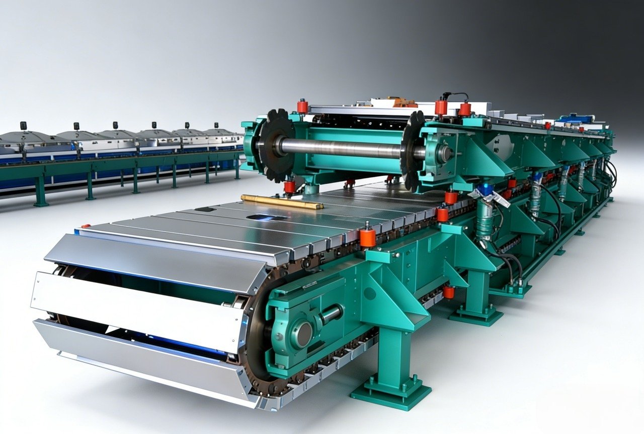
A continuous slabstock line looks simple in plan: polyol blend, isocyanate, water, catalysts, and additives are metered into a mixing head that traverses a moving trough; the reacting mixture is poured onto a paper-lined conveyor; the foam rises in a tunnel; and the block is cut and moved to curing. The utility load is less obvious because it is spread across a long production path rather than concentrated in one machine.
The main consumers are:
- Electrical power: metering pump and traversing drives, conveyor drives, tunnel exhaust fans, cooling-water pumps, mixing-head recirculation, raw-material day-tank agitation and heating, the cross-cut saw, and the control system.
- Compressed air: actuated valves, solenoid control, optional purge or cleaning circuits, and any pneumatic position control.
- Process cooling: mixing-head cooling to hold viscosity and temperature, and jacket or heat-exchanger control for raw-material day tanks.
- Ventilation: source capture at the pour zone, tunnel exhaust during rise and cure, and general exhaust for the cutting and block-aging areas.
- Instrument air or nitrogen: used only where the process or material storage requires blanket protection, particularly for moisture-sensitive raw materials.
Before moving ahead, do a first utility inventory for the intended line: rated hourly output, foam grades and density range, maximum block size, line speed range, and the site’s existing transformer, air-compressor, and chilled-water capacity. These are the inputs every utility calculation starts from.
Factory Building, Conveyor Space and Bay Layout
Conveyor length is not selected from a catalog line size; it comes from reaction time and line speed. The relationship is:
Conveyor length = line speed × time from pour to cut + safety allowance
If the line runs at 5 m/min and the slowest grade needs 8 minutes from pour to safe cutting, the conveyor alone requires 40 m before the saw; add room for the pour table, transition and discharge zones. Choose the grade that cures slowest, not the average grade.
Building height is driven by three stacked requirements: maximum block rise height, mixing-head traverse clearance above the block, and the ventilation hood or plenum above the traverse. A plant designed around the machine height alone will fight the exhaust system later. The block-aging area should also be included early because fresh slabstock generates heat and releases residual process vapors; that space must have adequate low-level air movement and clear separation from raw-material traffic.
Raw-material flow should not cross the finished-block path. The polyol and isocyanate unloading dock, day-tank area, and main electrical room need to be fixed before the conveyor axis is finalized. Isocyanate storage belongs in a separate, covered, drained area with containment; that means the building slab, curbs and drainage design must be settled before installation. Storage and handling of combustible raw materials should follow the applicable fire-code requirements, including NFPA 30 for containment and separation [1].
The same layout-and-investment sequence applies to a panel plant: power distribution, raw-material handling, and material flow are fixed before machines are installed. (https://haifengmachine.com/how-to-build-a-turnkey-sandwich-panel-factory-machine-configuration-layout-and-investment-planning/) covers how these decisions interact with machine configuration and total investment in a complete factory project.
Electrical Power, Compressed Air and Process Cooling
Electrical planning starts with the available voltage, phase count, frequency, and fault level at the factory main switchboard. Most industrial slabstock equipment is specified for three-phase supply at the site voltage — commonly 380 V, 400 V or 480 V — but the equipment order is not the time to discover a weak or non-standard feeder. The total installed load must be separated from the maximum simultaneous demand; tunnel fans, chilled-water pumps, tank agitation, and the saw can start at the same time as the metering line.
The control system should be fed separately from the big motor drives. Variable-frequency drives on fans and conveyors produce harmonics, so control power needs conditioning and surge protection. A frozen PLC during a pour is a production event, not just a nuisance.
Compressed air is the utility that creates more intermittent metering problems than it is credited for. The meter and mixing-head control air should be clean, dry, and oil-free. Choose solid-particle, pressure-dew-point, and oil limits from ISO 8573-1 [2]. The air specification should include the worst-case dew point at the machine inlet — not at the compressor outlet — because wet air can condense in a long, uninsulated header. Instrument air and process-quality air should not be shared with a general workshop loop that may carry water or oil.
Process cooling is also a stability parameter, not just a heat-removal task. The mixing head and day-tank jackets must hold raw-material temperature in a narrow operating window, because temperature swing changes viscosity, mix ratio, and cream time. Size the chiller for the warmest ambient day and the highest sustained output, not for average conditions. If the supply water is from a cooling tower, carry it through filtration and monitored make-up so mineral scale or biological fouling does not reduce heat transfer.
Do not let the civil contractor fix these numbers in isolation. Before ordering, compile the site limits: available power voltage, phase count and kVA; compressed-air pressure and ISO 8573-1 class; cooling-water supply temperature and available flow; and the local isocyanate exposure limit. That list can then be checked against the line’s metering, mixing-head traverse, and tunnel ventilation design. For a utility-to-line review, contact Haifeng Polyurethane Machinery at info@haifeng-automation.cn or WhatsApp: 86 13566296633.
Raw Material Handling, Isocyanate Safety and Environmental Protection
Polyol blends and isocyanates do not tolerate being treated as ordinary bulk liquids. Polyol day tanks usually need agitation and enough leaf or jacket heating to hold the temperature listed on the material TDS. Isocyanate storage must be covered, separated, level-monitored, and contained, because both TDI and MDI react with moisture and are respiratory and skin sensitizers.
The exposure limit drives the exhaust design. OSHA sets a 0.02 ppm ceiling permissible exposure limit for 2,4-toluene diisocyanate in general industry air contaminants [4], while NIOSH recommends a substantially lower 0.005 ppm time-weighted average limit [5]. A design based only on general air changes in the room is rarely adequate. Source capture at the mixing-head pour point, tunnel exhaust during rise and cure, and extraction at the cutting and aging areas should keep worker exposure below the applicable limit and preserve a safety margin.
Emission requirements also depend on location. Flexible polyurethane foam production can fall under national hazardous air pollutant rules, such as the U.S. EPA NESHAP for flexible polyurethane foam production [3]. The plant should verify which emission controls apply before the first pour, because adding a stack or scrubber later can trigger building modifications.
If any part of the line handles flammable solvents — for example, in purge or cleaning circuits — the area around the tanks, day tanks, and dispensing equipment may require hazardous-area classification and rated electrical equipment. Area classification should follow a standard such as IEC 60079-10-1 [6], and equipment in the classified zone should be selected to match the applicable regulation, including ATEX 2014/34/EU where applied [7].
Fresh slabstock is also a fire load. The exothermic reaction continues after the block leaves the tunnel, so fresh blocks should not be stacked densely in a corner without separation and temperature monitoring. Raw-material containment and drainage should prevent spills from reaching stormwater or general floor drains; that is both a fire-code and environmental requirement [1].
Utility Sizing Checklist and Common Planning Mistakes
The following checklist belongs in the RFQ or preliminary layout package. It is not a replacement for the machine builder’s thermal and pneumatic calculation, but it surfaces the decisions that create delay.
| Planning item | Required input | Common mistake |
|---|---|---|
| Electrical feeder | Available voltage, phase count, short-circuit level, maximum kVA | Sizing only for the machine nameplate while ignoring tunnel fans, pumps and the saw |
| Control power | Clean regulated supply, harmonic loading | Putting PLC and controls on the same noisy feeder as large VFD drives |
| Compressed air | ISO 8573-1 class, peak flow, header length | Specifying compressor-outlet quality but ignoring condensation in the plant header |
| Process cooling | Heat rejection at hottest ambient, water quality | Sizing for average summer rather than worst-case summer |
| Pour-zone ventilation | Local isocyanate OEL, capture hood performance | Using general ventilation instead of source capture |
| Tunnel and cutting exhaust | Rise/cure vapor level, clearing time, fire-code limits | Sizing for odor only rather than exposure and buildup |
| Raw-material storage | Bund capacity, separation, drainage, temperature control | Storing isocyanate and polyol side by side without containment or ventilation |
| Spill control | Containment, shut-off valves, stormwater protection | Allowing floor drains to run directly to the stormwater system |
| Hazardous-area assessment | Solvent vapor zones, vapor density, purge circuits | Installing non-rated motors and instruments near isocyanate or solvent transfer |
The most expensive utility mistakes are usually the least technical on paper: the transformer is too small for simultaneous starting, the exhaust is balanced for a clean empty room instead of a running line, and the cooling-water loop is sized for winter test runs. One frequent root cause is that utility data are collected before the foam grades and line speed are fixed. The utility design should be derived from the slowest grade, the longest block, and the hottest hour of operation.
Utilities that pass commissioning still degrade if air filtration, chiller maintenance and exhaust balancing are not scheduled after handover. (https://haifengmachine.com/continuous-pu-foam-production-line-maintenance-how-to-prevent-costly-downtime-and-defects/) covers how service-side failures turn into foam defects and production downtime.
Bring utility data to the equipment discussion early. You do not need a complete building design; you need the service limits: available power, voltage and phase count, compressed-air class, cooling-water supply conditions, exhaust capacity, and the local chemical exposure limit. Haifeng Polyurethane Machinery can map these against the continuous line’s metering station, mixing-head traverse, tunnel and cutting layout. Email info@haifeng-automation.cn or WhatsApp: 86 13566296633.
Frequently Asked Questions About Continuous PU Slabstock Utility Planning
How much electrical power does a continuous slabstock line need?
There is no single figure because the line combines small precision drives with large ventilation and pumping loads. Start with the total required transformer capacity at maximum simultaneous demand. The main switchboard must cover metering-pump drives, conveyor drives, tunnel exhaust fans, cooling-water pumps, raw-material agitation, heating, and the cutting saw. If possible, ask the utility or consultant for short-circuit capacity and existing spare feeder capability before the machine builder fixes the drive list.
What compressed air quality is required for the controls and mixing head?
The control air should be clean, dry, and oil-free to protect proportional and solenoid valves. The specification should be written as an ISO 8573-1 purity class covering particle content, pressure dew point, and oil content [2]. The pressure dew point should be met at the machine inlet after the widest header run; moisture condensed in the pipe is still moisture at the valve.
What is the main isocyanate safety issue in utility planning?
The main issue is not storage volume; it is airborne exposure. TDI and MDI are sensitizers, and the pour zone, tunnel, cutting, and aging areas must be engineered for source capture and negative pressure. OSHA sets a 0.02 ppm ceiling limit for 2,4-TDI, while NIOSH recommends a lower 0.005 ppm time-weighted average [4][5]. Ventilation should be based on the applicable local limit plus a margin, not on a general air-change target.
How is conveyor length determined?
Use the formula: conveyor length equals line speed multiplied by the time from pour to safe cutting, plus a discharge allowance. The design speed and time should come from the slowest-curing foam grade the plant will run. If the line runs faster for low-density foam, the conveyor length must still accommodate the longest cure time in the product range.
What utilities do plant owners most often under-size?
The common gaps are exhaust capture at the pour zone, stable process cooling for warm-weather operation, compressed-air quality at the machine inlet, and electrical reserve for simultaneous fan and pump starts. Raw-material bunding and separation are also underestimated because they affect civil work, not machine installation.
References
[1] National Fire Protection Association, NFPA 30: Flammable and Combustible Liquids Code, 2024 edition.
[2] International Organization for Standardization, ISO 8573-1: Compressed Air — Part 1: Contaminants and Purity Classes, current edition.
[3] U.S. Environmental Protection Agency, National Emission Standards for Hazardous Air Pollutants: Flexible Polyurethane Foam Production, 40 CFR Part 63, Subpart III.
[4] U.S. Occupational Safety and Health Administration, 29 CFR 1910.1000, Air Contaminants, Table Z-1: 2,4-Toluene Diisocyanate.
[5] National Institute for Occupational Safety and Health, NIOSH Pocket Guide to Chemical Hazards: Toluene-2,4-Diisocyanate, current edition.
[6] International Electrotechnical Commission, IEC 60079-10-1: Explosive Atmospheres — Part 10-1: Classification of Areas — Explosive Gas Atmospheres, current edition.
[7] European Parliament and Council, Directive 2014/34/EU on Equipment and Protective Systems Intended for Use in Potentially Explosive Atmospheres.
If you’re interested, check out these related articles:
How to Reduce Waste in PU Shoe Production
How to Choose the Right PU Shoe Moulding Machine
The Ultimate Guide to Low-Pressure Foaming Machines for PU Elastomers
What Machines Are Needed for a PU Safety Shoe Production Line?
High Pressure vs. Low Pressure Polyurethane Foam Machine: How to Choose the Right One for Your Production